2OM-1751-003w_G5S.pdf - 第106页
2OM-1751 1-54 1303-001 T ape Length The condition for displaying the alarm for splicing, is set based on the remaining tape length. PCB Count The condition for displaying the alarm for splicing, is set based on the numbe…
2OM-1751
1-531303-001
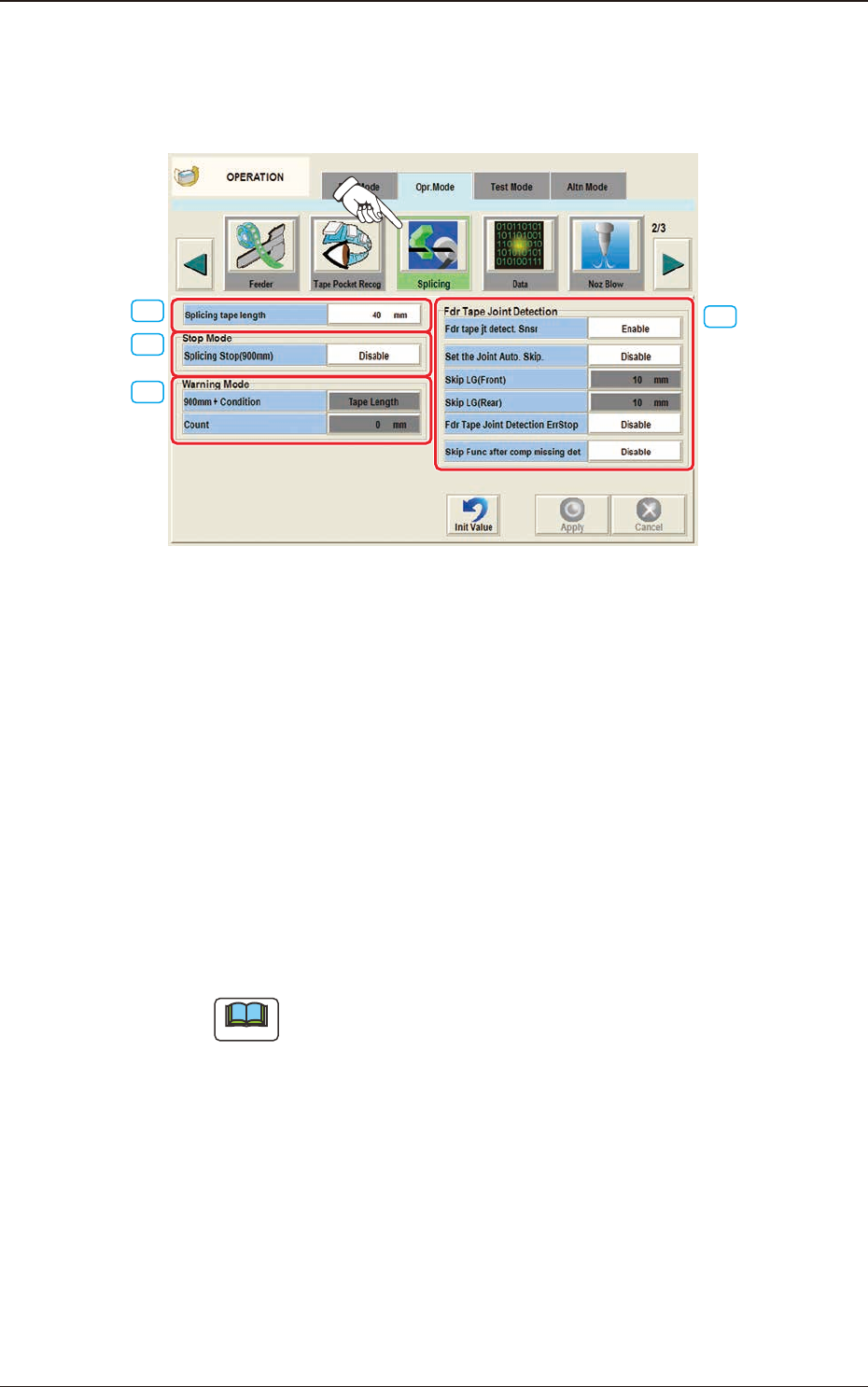
4.2.8 Splicing
When the [Splicing] button is pressed on the "Opr.Mode" tab sheet, the following
window appears.
[3]
[2]
[1]
[4]
F2A35
[1] Splicing tape length
The splicing tape length is set in this text box.
[2] "Stop Mode" Group Box
Splicing Stop (900 mm)
The [Enable] or the [Disable] button can be selected to determine whether or
not the machine should be stopped for tape splicing required when the length
of the remaining tape becomes shorter than 900 mm.
[3] "Warning Mode " Group Box
The following conditions can be added to the criterion (Length of Remaining
Tape: 900 mm) to set the time to issue a warning of splicing need.
Note
It cannot be specied to issue a splicing warning message with the length
of the remaining tape shorter than 900 mm.
900 mm + Condition
The condition for displaying the alarm for splicing, is selected from the
following items.
4.2 "Opr.Mode" Tab Sheet

2OM-1751
1-541303-001
Tape Length
The condition for displaying the alarm for splicing, is set based on the
remaining tape length.
PCB Count
The condition for displaying the alarm for splicing, is set based on the
number of producible PCBs.
[Count] Button
When this button is pressed, it becomes possible to set the number of PCBs
(PCBs that can be produced) as a condition to issue a splicing warning
message.
[4] "Fdr Tape Joint Detection" Group Box
Fdr tape jt detect. Snsr
"Enable" or "Disable" is selected for the joint seam detection sensor.
Set the joint Auto. Skip.
"Enable" or "Disable" is selected for the "Set the joint Auto. Skip", in this
text box.
Skip LG(Front)
The skip start position from the joint is set in this text box.
Skip LG(Rear)
The skip end position from the joint is set in this text box.
Frd Tape Joint Detection ErrStop
When an error (E3) is caused in the tape feeder, the machine is stopped.
Reference
Refer to "SIGMA-G4/G5 Tape Feeder Instruction Manual" for the derails
of the error codes for the tape feeder.
Skip Func after comp missing det
"Enable" or "Disable" for the Skip after "No Component" detected, is
selected in this selection box.
4.2 "Opr.Mode" Tab Sheet
2OM-1751
1-551303-001
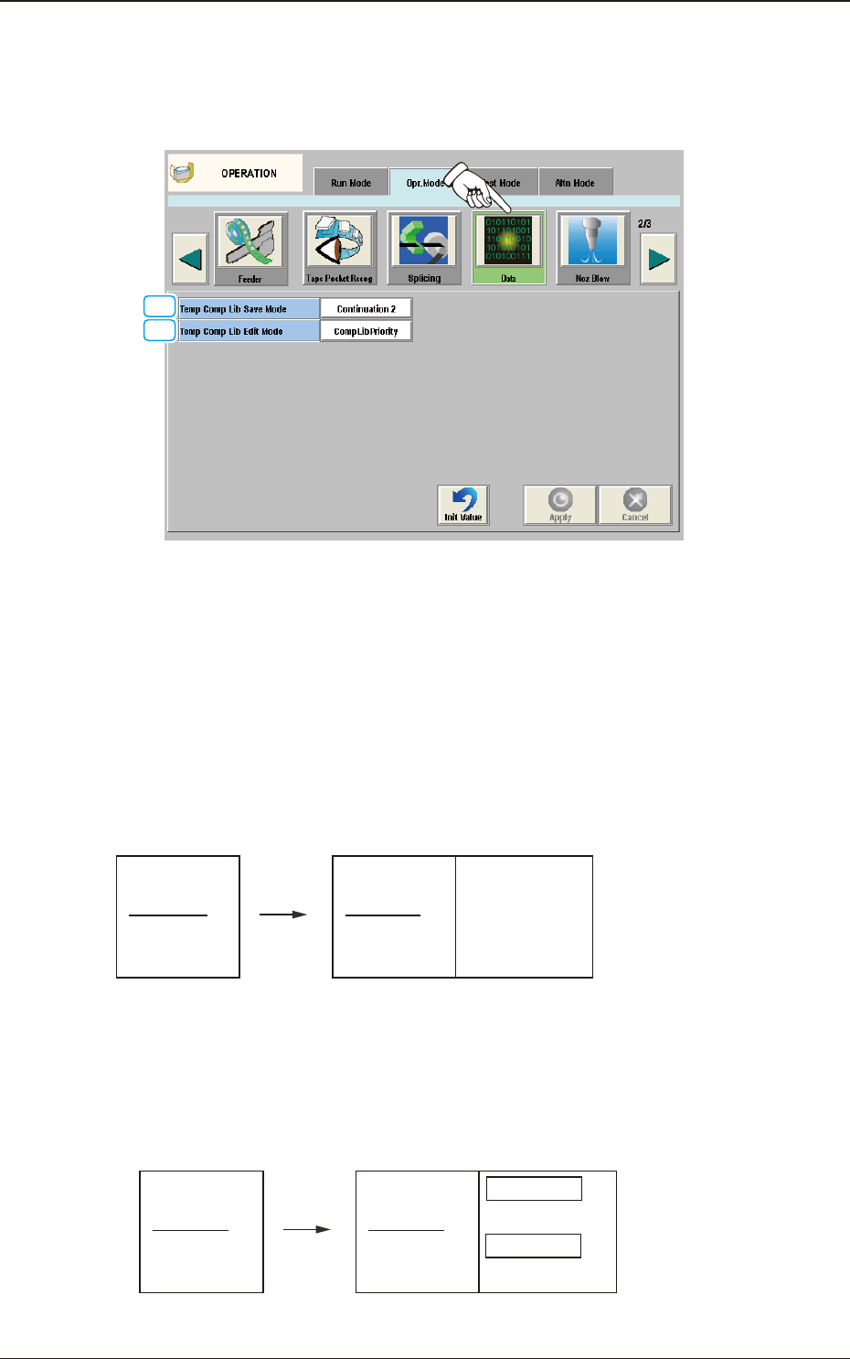
4.2.9 Data
When the [Data] button is pressed on the "Opr. Mode" tab sheet, the following
window appears.
[2]
[1]
F2A36
[1] Temp Comp Lib Save Mode
One of the following options can be selected for saving the carrier data.
[Standard] Button
When selected, the data saving operation continues only when the component
data is perfectly consistent.
(Standard)
(Before Changeover)
101 AAA
102 BBB
103 CCC
104 DDD
(After Changeover)
All are initialized because there is a
difference in 102.
101 AAA
102 DDD
103 CCC
104 DDD
Initialized
Initialized
Initialized
Initialized
Simplified Packaging
Direction Change Function
F2A37
[Continuation 1] Button
The system keeps on saving only the component data that has the same ID.
(Continuation 1)
(Before Changeover)
101 AAA
102 BBB
103 CCC
104 DDD
(After Changeover)
The 102 data is initialized because
there is a difference.
The 104 data is cleared because
it is not used.
The other data is continued.
101 AAA
102 DDD
103 CCC
104
Continued
Initialized
Continued
Cleared
Simplified Packaging
Direction Change Function
F2A38
4.2 "Opr.Mode" Tab Sheet