2OM-1751-003w_G5S.pdf - 第171页
2OM-1751 2-49 1303-001 3.5 PL Head/Nozzle (E01) Nozzle Place Data When the [Nozzle Place] tab is pressed in the "PL Head/Nozzle" window, the following tab sheet appears. F2B40 (E01_01) Nozzle Place Head1 and 2 …

2OM-1751
2-481303-001
(D03_05)
Avoid comp deviation
Carrier, Stage inside, Output
The following items are set for "Reload", "Stage Inside" and "Discharge".
Speed 1 [mm/sec]
The PCB is transferred at the specied speed.
Speed 2 [mm/sec]
The PCB transferred at the Speed 1, is detected using the speed reduction
sensor and the speed is reduced to the "Speed 2"specied here in this text
box.
Acceleration [G]
The acceleration to reach the speed specied in "Speed 1"is set in this text
box.
(D03_06)
Stop position control
Carrier, Positioning 1, Positioning 2, Output
The following items are set for "Reload", "Positioning 1", "Center",
"Positioning 2"and "Discharge".
Timer [msec]
The time period for the PCB detected using the speed reduction sensor, to
reach the reduced speed specied in "Speed 2", is set in this text box.
•
Initial Value:350 [msec]
Position [mm]
The distance from the position of the PCB detected using the stop sensor
to the PCB stop position, is set in this text box.
3.4 Control
2OM-1751
2-491303-001
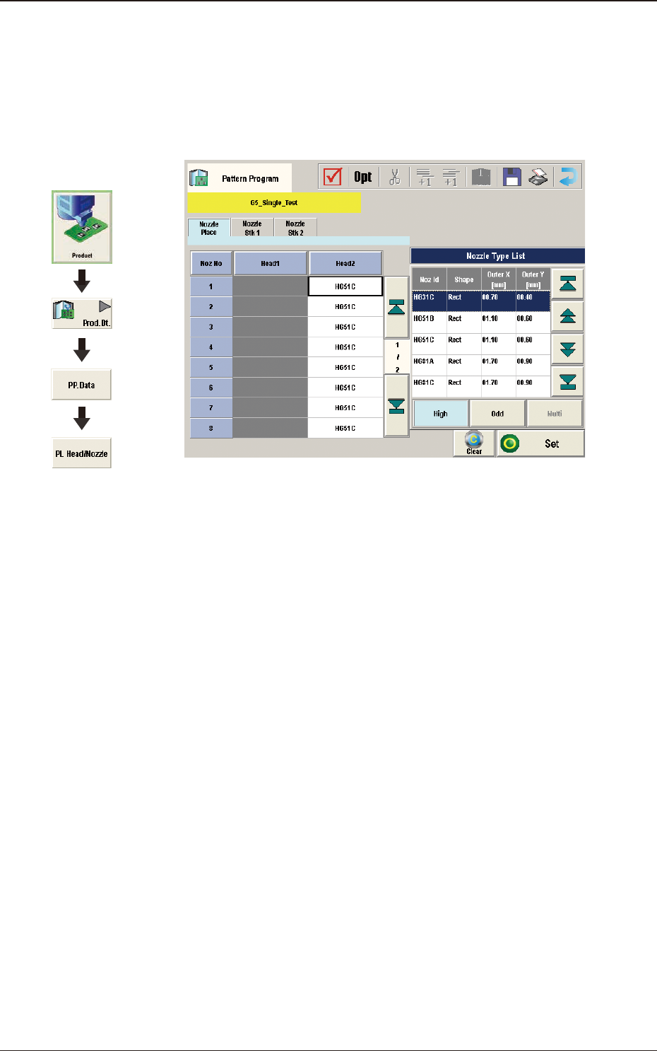
3.5 PL Head/Nozzle
(E01) Nozzle Place Data
When the [Nozzle Place] tab is pressed in the "PL Head/Nozzle" window,
the following tab sheet appears.
F2B40
(E01_01) Nozzle Place
Head1 and 2
Nozzle No. 1 to 15
This data is used to allocate the nozzles to the specied positions (Nozzle
Allocation Nos.) on the heads.
Graphic
Development
3.5 PL Head/Nozzle
2OM-1751
2-50
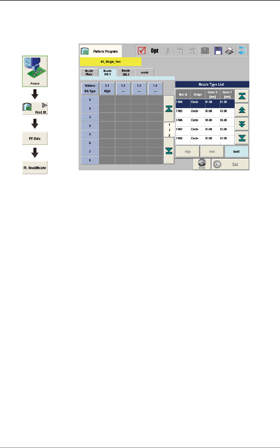
(E02) Nozzle Stk 1, 2 data
When the [Nozzle Stk 1] or [Nozzle Stk 2] tab is pressed on the "PL Head/
Nozzle" window, the following tab sheet appears.
F2B41
(E02_01) Nozzle Stk 1, 2
Address Stk Types 1 to 15
Using these parameters, the nozzles are housed in the specied positions
(address stocker type) in the nozzle stocker.
High
: 1 to 15
Multi
: 1 to 9
1303-001
3.5 PL Head/Nozzle
Graphic
Development