2OM-1751-003w_G5S.pdf - 第269页
2OM-1751 5-13 1303-001 [ ] Button When pressed the currently selected component is displayed. Blue Circle : It shows that the component is recognized normally. Red Circle : It shows that there is an error in the componen…

2OM-1751
5-121303-001
[
] button :
Image Enlargement Mode
After changing to the image enlargement mode using the
[
] button (the shape of the pointer is changed to ),
when the image to be enlarged is touched, or the left button
of the mouse is clicked on the image, the image is enlarged
from the pointer position as the center.
When the image is to be enlarged with its position xed,
place the pointer on the center of the image before the
enlargement operation.
[
] Button :
Image Reduction Mode
After changing to the image reduction mode using the
[
] button (the shape of the pointer is changed to )
when the image to be reduced is touched, or the left button
of the mouse is clicked on the image, the image is reduced
from the pointer position as the center.
When the image is to be reduced with its position xed,
place the pointer on the center of the image before the
reduction operation.
[
] Button :
Image Fitting Mode (the image is displayed fully using the
recognition image display domain).
After changing to the image tting mode using the [
]
button (the shape of the pointer is changed to
), when
the image to be t is touched, or the left button of the
mouse is clicked on the image, the image is displayed
fully using the recognition image display domain, from the
pointer position as the center.
When the image is to be displayed in the image tting mode
with its position xed, place the pointer on the center of the
image before the image tting operation.
[
] Button :
Image Real-Size Display Mode (Captured image is
displayed in real-size).
After changing to the image real-size display mode using
the [
] button (the shape of the pointer is changed to
), when the image to be displayed in real-size is touched,
or the left button of the mouse is clicked on the image, the
image is displayed in real-size from the pointer position as
the center.
When the image is to be displayed in real-size with its
position xed, place the pointer on the center of the image
before the image real-size display operation.
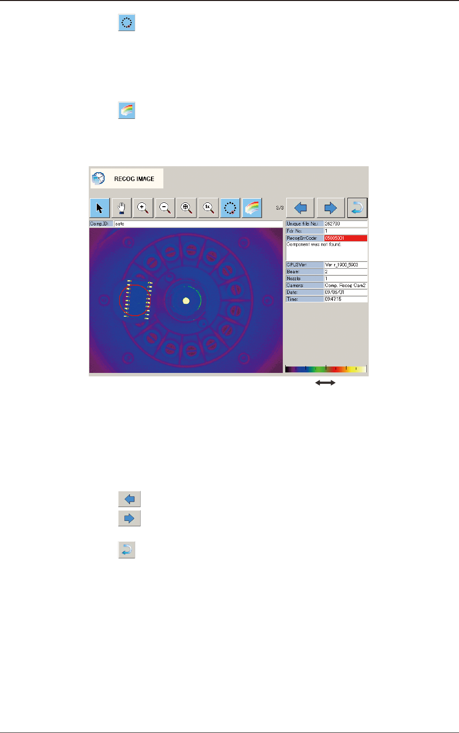
6.2 "RECOG IMAGE" Conrmation Window
2OM-1751
5-131303-001
[
] Button
When pressed the currently selected component is displayed.
Blue Circle
: It shows that the component is recognized normally.
Red Circle
: It shows that there is an error in the component recognition.
[
] Button
Using this button, the black and white recognized image is changed to color
display for easy to see.
Dark Bright
F2E13
[2] Recognized Image Display Pane
In this pane, the recognized image is displayed.
[3] Recognized Image Change Button
[
] Button
: When pressed, the preceding component is displayed.
[
] Button
: When pressed, the next component is displayed.
[4] [
] Button
When pressed, the "RECOG IMAGE" window is returned.
[5] Recognized Image Details
The details of the recognized image are displayed.
6.2 "RECOG IMAGE" Conrmation Window

2OM-1751
5-141303-001
[6] File Name
The le names where recognized images have been saved automatically, are
displayed.
The name to be saved is added to the le name. Therefore, using the le
name, the recognition processing contents can be checked.
File Name Example
••••
.hdb
Saving object name
Saving object
Saving object name
Component Recognition
DA_
PEC Recognition
MA_
Basis Mark Recognition
KA_
Component Recognition Test
DT_
PEC Recognition Test
MT_
Stocker Nozzle Check
NE_
Nozzle ID Recognition
NO_
Bad Mark Recognition (Option)
BM_
Bad Mark Recognition Test (Option)
BT_
2-D Barcode Recognition (Option)
BC_
2-D Barcode Recognition Test (Option)
BE_
Nozzle Recognition
TN_
Camera Magnication Teaching
TC_
Basis Mark Teaching
TB_
Lighting Teaching
TL_
PEC Recognition Camera & Beam OFFset
TM_
Feeder OFFset
TF_
Nozzle Stocker OFFset
TS_
Traverse Drawer Position OFFset (Option)
TT_
Feeder Pocket Recognition
TP_
Camera OFFset
TA_
Head Rotational Center, Basis Mark Position
TH_
Head Rotational Axis OFFset
TR_
Coplanarity Check Unit OFFset (Option)
TO_
T2E2
6.2 "RECOG IMAGE" Conrmation Window