2OM-1751-003w_G5S.pdf - 第157页
2OM-1751 2-35 1303-001 (C05_05) M-X, M-Y Using these selection boxes, the support pin placement coordinates (M-X, M-Y) are setup. Coord X, Coord Y The set support pin coordinates are displayed in these data boxes. • Data…
2OM-1751
2-34
(C05_02)
Support Pin
Using this selection button, it is set whether or not the support pins are setup
automatically in the pattern program change operation.
(C05_03)
The number of Pin using
The number of pins to be used in the automatic operation is set in this
selection box.
•
Data Input Range
1 to 20 pins
(C05_04)
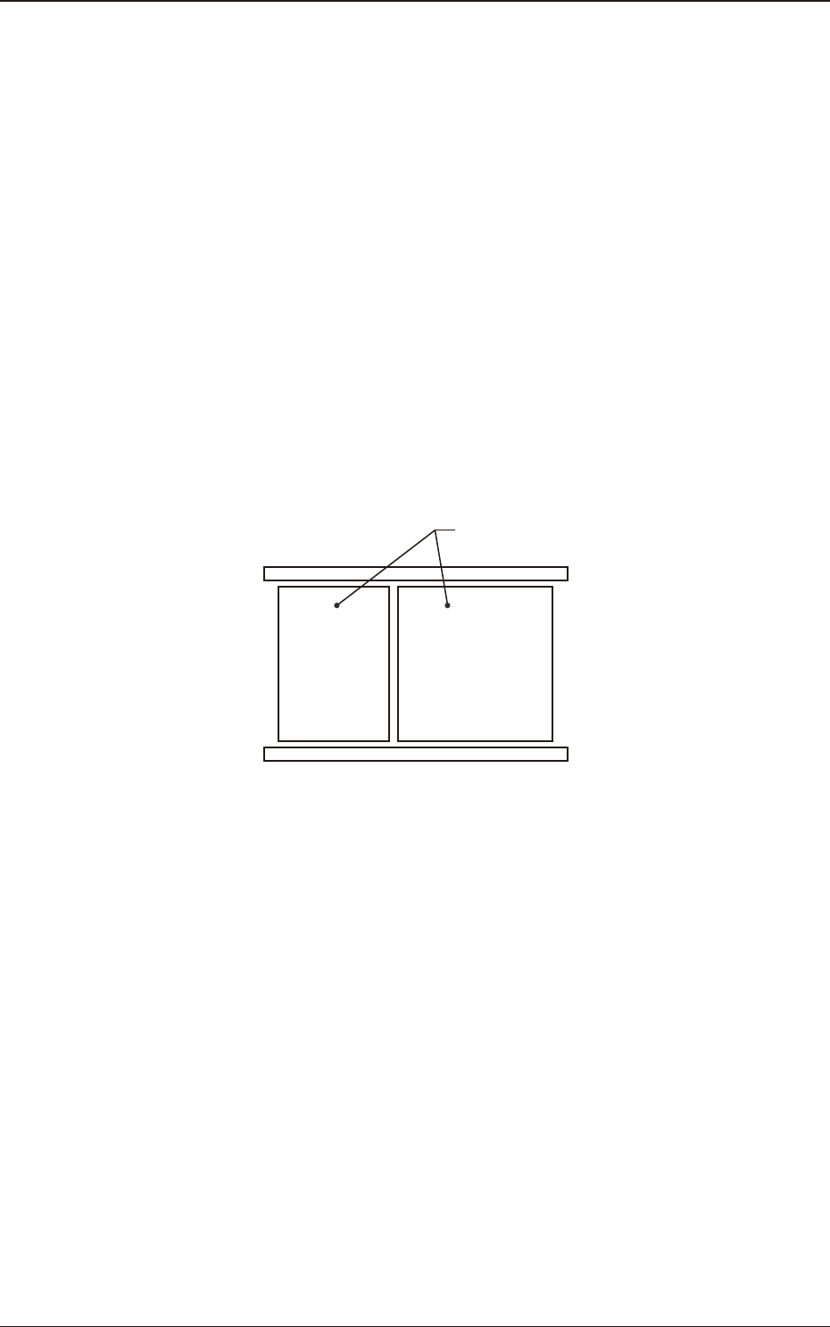
Table
Using this selection box, it is set that the backup base where the support pins
are placed, is in the output or input.
Input Output
Backup Base
F2B27
1303-001
3.3 Operation
2OM-1751
2-351303-001
(C05_05)
M-X, M-Y
Using these selection boxes, the support pin placement coordinates (M-X,
M-Y) are setup.
Coord X, Coord Y
The set support pin coordinates are displayed in these data boxes.
•
Data Input Range
Input
M-X
: 1 to 30
M-Y
: 1 to 50
Output
M-X
: 1 to 30
M-Y
: 1 to 50
Y
X
Input Output
F2B28
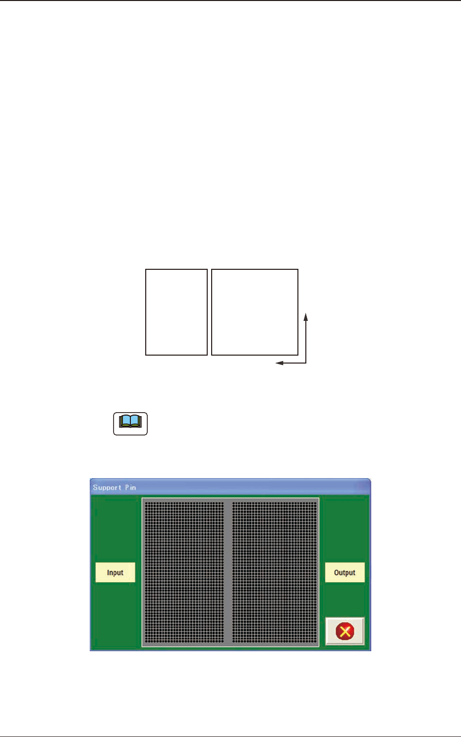
Note
When the [Pin] button is pressed, the "Support Pin" dialogue box is opened
and the support pin positions can be checked.
When the [Clear] button is pressed, the support pins with the selected Nos.
are cleared.
F2B29
3.3 Operation
2OM-1751
2-361303-001
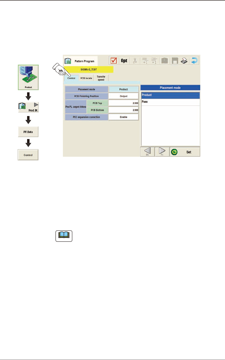
3.4 Control
(D01)
Control Data
When the [Control] tab is pressed in the "Control" window, the following tab
sheet appears.
F2B30
(D01_01)
Placement Mode
"Product" or "Pass" is selected for the placement mode in this pane.
Normally, "Product" is selected.
Product
: When selected, the placement operation is performed.
Pass
: When selected, the PCB is passed without placement.
Note
When the pattern program set to "Pass", is setup on the Pattern Program
Data, the vacuum pump is automatically turned OFF.
Graphic
Development
3.4 Control