2OM-1751-003w_G5S.pdf - 第152页
2OM-1751 2-30 1303-001 (C03) Operation Data When the [Operation] button is pressed in the "Operation" window, the following window appears. F2B23 Graphic Development 3.3 Operation

2OM-1751
2-291303-001
(C02_06)
Mark Level
Set the threshold levels of the ducial marks. In normal cases, set "High".
High
: Both identity and similarity between the shape of a ducial mark
and the real image are detected on a high level.
Middle
: Either identity or similarity between the shape of a ducial mark
and the real image are detected on a middle level.
Low
: Both identity and similarity between the shape of a ducial mark
and the real image are detected on a low level.
Note
(a)
Identity
: Degree of identity between the shapes of the specied
mark and the real image (including the size)
(b)
Similarity
: Degree of similarity between the shapes of the specied
mark and the real image
(C02_07)
Angle [deg]
Set the angle at which a ducial mark should be turned clockwise.
•
Data Input Range
0°, 90°, 180°, 270°
Note
(a) A numerical value must be entered in increments of 90°.
When a value other than the specied increments is entered, the
"Information" window appears, indicating that the entered value
(angle) is changed to "0°", "90°", "180°" or "270°".
(b) When "Thru Hole / Land" is selected in the "Mark Type" (C02_02)
combo box, the color of the angle cell is highlighted and "0 deg" is set
in the "Angle [deg]" text box.
(C02_08)
Lighting Level
Coax, Ring, Option
The brightness level for each lighting is selected from the following items.
Off Std -80% -60% -40% -20%
+20% +40% +60% +80% Auto
3.3 Operation
2OM-1751
2-301303-001
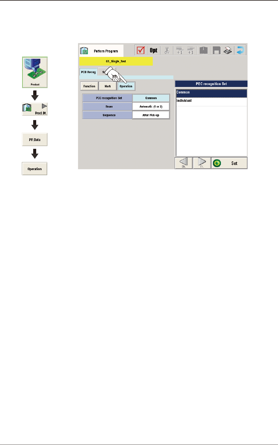
(C03) Operation Data
When the [Operation] button is pressed in the "Operation" window, the
following window appears.
F2B23
Graphic
Development
3.3 Operation

2OM-1751
2-311303-001
(C03_01)
PEC recognition Set
Common
: When selected, the PEC recognition is performed with
the common setting to the both lines.
Individual
: When selected, the PEC recognition is performed with
different setting for each machine.
(C03_02)
Beam
It can be determined which beam should be used for the global and image
PEC recognition operations.
Beam 1
: Select this when only Beam 1 should be used for PEC
recognition operations.
Beam 2
: Select this when only Beam 2 should be used for PEC
recognition operations.
Automatic (1 or 2)
: The machine determines which beam (Beam 1 or 2)
is more suitable for PEC recognition operations and
selects the better one.
Both Beam
: Select this when both beams (Beams 1 and 2) should
be used for PEC recognition operations.
Note
As for the local PEC recognition, the PEC recognition operations are
performed with the beam by which components are placed regardless of
this designation of the PEC recognition beams.
(C03_03)
Sequence
Set one of the following options to specify the timing of PEC recognition
implementation. It is recommended that "After Pick-up" should be set in
normal cases.
Note
The components must meet the following requirements.
When "After Pick-up" is selected, a component is picked up and the
component recognition is performed on the component while the PCB is
being transferred to the PCB positioning section.
Since the component is already picked up, it can be placed soon after the
PEC recognition operation is performed, shortening the time to nish a
PCB.
After Pick-up
: The PEC recognition operation is performed after a
component is picked up.
Before Pick-up
: The PEC recognition operation is performed before a
component is picked up.
This parameter should be selected when the PEC
recognition operation cannot be performed with a
component being picked up.
3.3 Operation