5OM-1064-001.pdf - 第19页
Section 2 Adjustment of P .C.B. Positioning Section 9910-001 2-1 Tg0250-PM-MD

Automatic Sizing
Button
Power Switch
Adjustment Procedure
(1) Open the display which has the most prominent moire effect.
(2) Select “Moire” from the submenu dialog box.
(3) Press “Center” of the operation pad and open the “ON/OFF Selection”
dialog box.
(4) Select “ON” and press “Center” of the operation pad. The display for
moire correction appears on the screen.
Note: When “ON” is selected for the moire correction function, the repro-
duced picture may look as if it is wavering.
Select “OFF” when the stability and distinction of the reproduced pic-
ture are required prior to the correction of moire effect.
Ref.: The moire effect can also be reduced by adjusting the incorrect aspect
ratio (insufficient width and height) at the “Size” dialog box.
3.2 Color Adjustment
Standard Mode Adjustment
• Select “Color Temperature” and adjust the colors of the reproduced picture.
The color temperature can be selected in “500K” increments, with 4000K
as the minimum temperature and 10000K as the maximum one.
(The default “9300K” is exceptional.)
Adjustment Procedure
(1) Follow the hierarchical sequence - “Screen Manager” → “Color Adjust-
ment” → “Standard” → “Color Adjustment”.
(2) Move “Arrow” right and left by pressing the operation pad right and left
to set the color temperature.
(3) After the desired color temperature is selected, press “Center” of the op-
eration pad to determine the selected temperature. The submenu dialog
box resumes.
4. Adjustment Lock Function
• Use the adjustment lock function to lock the adjusted settings.
After the adjusted settings are locked, the settings cannot be changed tem-
porarily with the operation pad on the front panel.
Setting
Turn on the power switch of the monitor while pressing the automatic sizing
button.
Fig. 1.13
Cancellation
Turn off the power switch once. Then, turn it on again while pressing the
automatic sizing button.
4. Adjustment Lock Function
0005-002 1-8 Tg0250-PM-MD

Section 2
Adjustment of P.C.B. Positioning Section
9910-001 2-1 Tg0250-PM-MD
Section 2 Adjustment of P.C.B. Positioning Section
• The direction of the P.C.B. stopper block is adjusted in compliance with the
setting upon shipment of the machine.
When setting is changed, it is required to change the direction of the P.C.B.
stopper block according to the changed setting.
• See the figures depicted in “6.3 P.C.B. Transfer in Volume 1” for the direc-
tion of the P.C.B. stopper block.
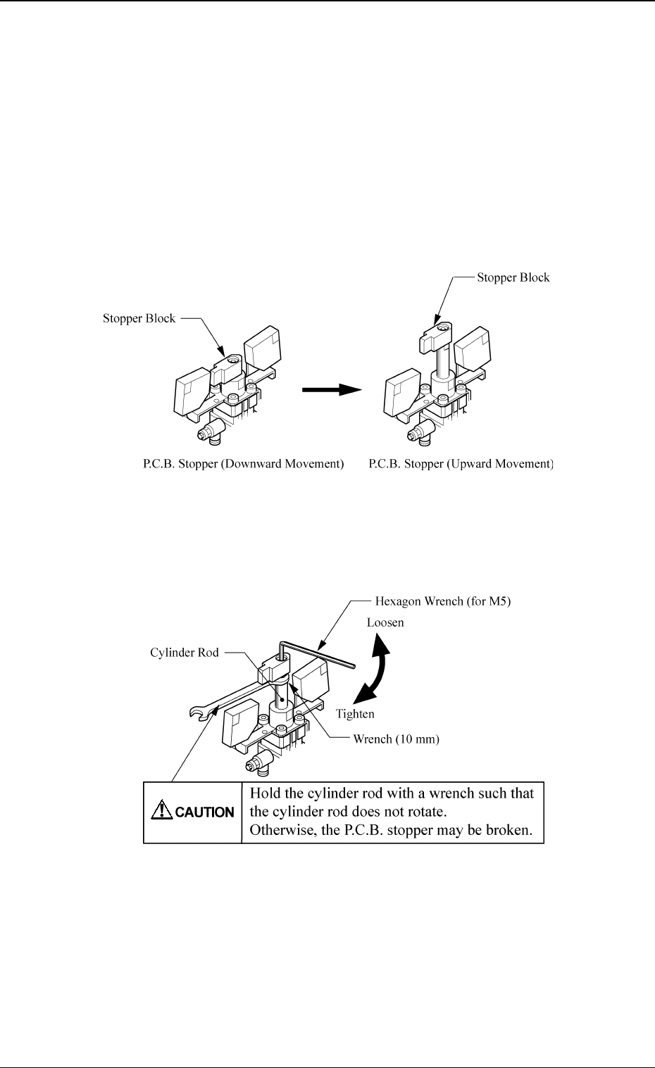
Procedure for Direction Change of Stopper Block
(1) Move up the P.C.B. stopper and shut off the power supply.
Fig. 2.1
(2) Hold the cylinder rod with a wrench and remove the bolt fastening the
stopper block.
Fig. 2.2
(3) Change the direction of the stopper block by 180° and insert it into the
cylinder rod.
(4) Hold the cylinder rod with a wrench and tighten the bolt fastening the
stopper block.
Section 2 Adjustment of P.C.B. Positioning Section
0005-002 2-2 Tg0250-PM-MD