5OM-1626-001_w.pdf - 第153页
5OM-1610 4-38 091 1-001B(M913WR---0003) Recognition Connection Diagram 3 Shield Shield U94 U95 CH5 Action A Phase Inpu+ B36 B35 B34 B33 B27 B26 B25 CH6 Action B Phase Input- CH6 Action A Phase Inpu+ CH6 Action B Phase In…
5OM-1610
4-370911-001C(M913WR---0002)
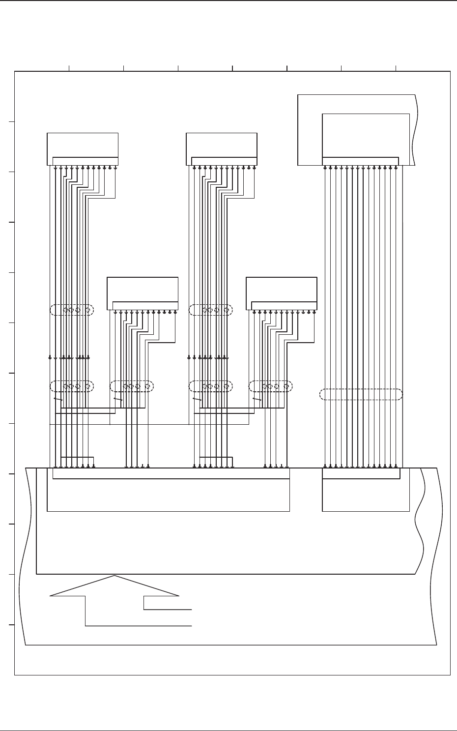
Recognition Connection Diagram 2
14
13
CN3
1
3
2
5
4
6
7
8
9
10
11
12
GND
+5V
4
2
7
10
1
5
8
11
3
6
9
12 VD-
HD+
Video-
TRGER
GND
HD-
GND
-
VD+
+12V
Video+
-
-
Video+
+12V
VD+
-
GND
HD-
GND
TRGER
Video-
HD+
VD-12
9
6
3
11
8
5
1
10
7
2
4
VIDEO-Cam3
CTRL2-Cam3
HDrive-Cam3
VDrive-Cam2
VIDEO-Cam1
VDrive-Cam4
HDrive-Cam4
CTRL1-Cam3
VDrive-Cam3
GND
CTRL1-Cam2
CTRL2-Cam2
CTRL1-Cam1
CTRL1-Cam4
CTRL2-Cam4
+12V
VIDEO-Cam4
CTRL2-Cam1 24
22
21
20
19
18
16
15
2
13
12
11
10
9
7
4
3
1
25
26VDrive-Cam1
HDrive-Cam1
CAMERA
PIO
X9201
6
1
19
3
8
7
17
20
13
12
9
18
2
10Trig_3 (IN)
PIO_0
Strobe_1(OUT)
Trig_2 (IN)
PIO_1
PIO_3
Strobe_3(OUT)
Trig_0 (IN)
Trig_1 (IN)
PIO_2
Strobe_2(OUT)
+5V_PIO
X9202
-X6101
-X6101
X9503
U95
+12V 23
GND 6
VIDEO-Cam2 5
HDrive-Cam2 17
-X13601
GND 8
GND 14
U92
-X13601
ROBOT CABLE
ROBOT CABLE
PCI-bus
Slot3
Strobe_0(OUT)
GND
:2
:12
:9
:6
:3
:11
:8
:5
:1
:7
:4
:2
:12
:9
:6
:3
:11
:8
:5
:1
:7
:4
4
2
7
10
1
5
8
11
3
6
9
12 VD-
HD+
Video-
TRGER
GND
HD-
GND
-
VD+
+12V
Video+
P.S
4
2
7
10
1
5
8
11
3
6
9
12 VD-
HD+
Video-
TRGER
GND
HD-
GND
-
VD+
+12V
Video+
P.S
-X3601
-X3601
:15
:15
B61(1)
B61(2)
CPU1
B36(1)
B36(2)
1
2 3 4 5 6 7 8 9 10 11 12
A
B
C
D
E
F
G
H
PEC Recognition Light ON Signal 2
PEC Camera Capture Trigger 1
PIO_3(General Purpose)
PIO_2(General Purpose)
PEC Camera Capture Trigger 2
Component Camera Capture Trigger 2
PIO_0(General Purpose)
PEC Recognition Light ON Signal 1
Component Recognition Light ON Signal 2
Component Recognition Light ON Signal 1
PIO_1(General Purpose)
Component Camera Capture Trigger 1
Connector Case
Lighting Control Board
Connector Case
PEC Recognition Camera (2)
Component Recognition Camera (2)
Connector Case
PEC Recognition Camera (1)
Component Recognition Camera (1)
Connector Case
Connector Case
Connector Case
Connector Case
(Frame Grabber 1)
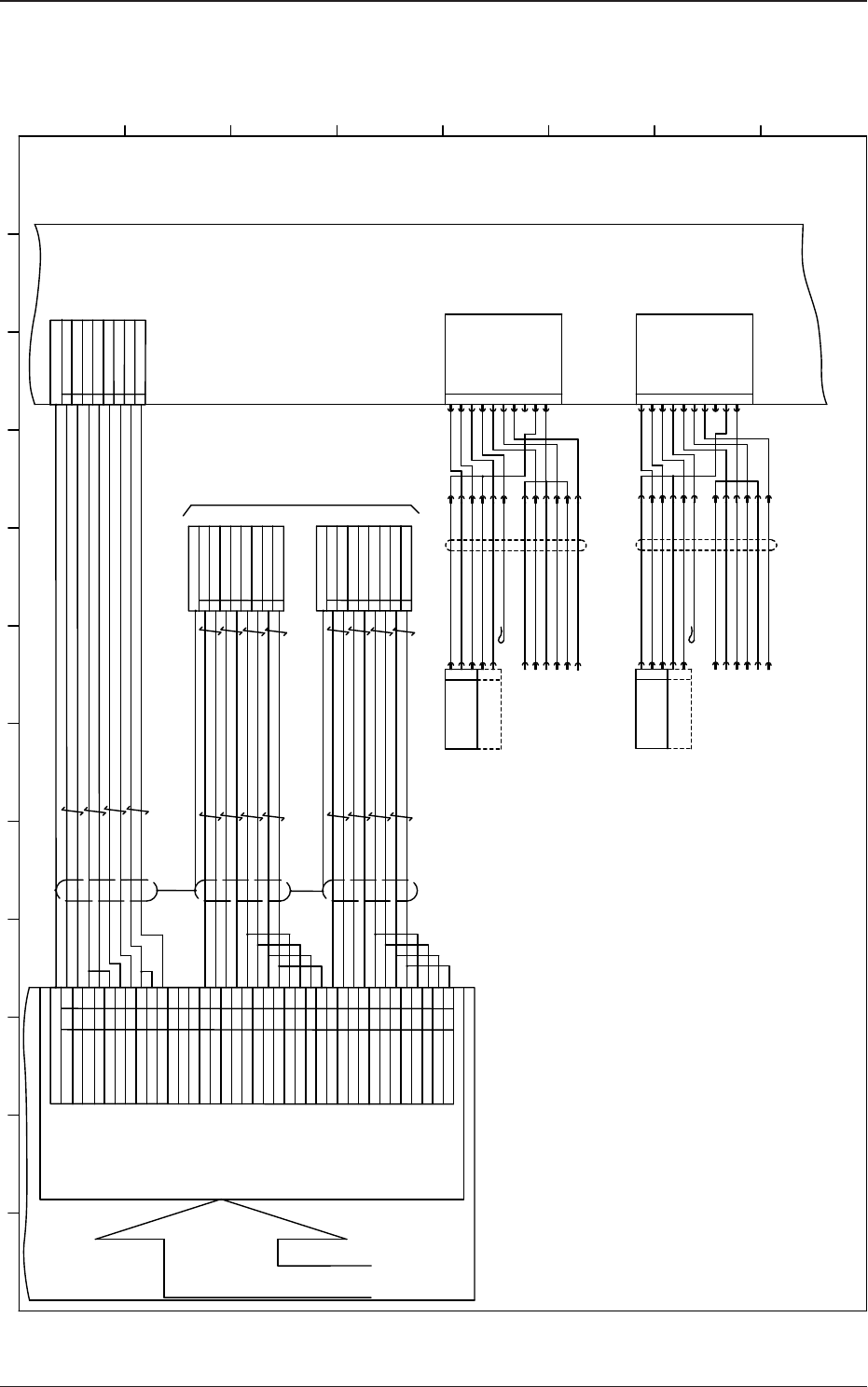
5OM-1610
4-380911-001B(M913WR---0003)
Recognition Connection Diagram 3
Shield
Shield
U94
U95
CH5 Action A Phase Inpu+
B36
B35
B34
B33
B27
B26
B25
CH6 Action B Phase Input-
CH6 Action A Phase Inpu+
CH6 Action B Phase Input+
CH5 Action B Phase Input-
CH6 Action A Phase Inpu-
CH5 Action B Phase Input+
CH5 Action A Phase Inpu-
72
71
70
69
64
63
62
61
B28
CH2 Action A Phase Inpu+
B20
B19
B18
B17
A35
A34
A33
CH4 Action B Phase Input-
CH4 Action A Phase Inpu+
CH4 Action B Phase Input+
CH2 Action B Phase Input-
CH4 Action A Phase Inpu-
CH2 Action B Phase Input+
CH2 Action B Phase Input-
16
15
14
13
80
79
78
77
A36
A20
CH6 Single Shot Output
FG
Connector Case
GND
TRIG-Y1
TRIG-Y2
GND
TRIG-X1
5
4
3
2
1
21
22
23
24
29
30
31
32
41
91
92
93
43
CH4 Single Shot Output
CH2 Single Shot Output
CH0 Action A Phase Input-
CH0 Action A Phase Input+
CH0 Action B Phase Input+
GND
GND
CH5 Single Shot Output
A04
B04
B05
B06
CH1 Action A Phase Input-
CH0 Action B Phase Input-
CH1 Action B Phase Input+
CH1 Action A Phase Input+
CH1 Action B Phase Input-
A08
A17
A18
A19
A25
A27
A28
A29
Connector Case
4
3
2
1
GND
GND
TRIG-X2
8
7
6
Connector Case
45
CH0 Single Shot Output
A04
GND
CH1 Single Shot Output
GND
44A05
GND
Connector Case
4
3
2
1
Y1 Action A Phase Input+
Y1 Action A Phase Input-
X1 Action A Phase Input+
X1 Action A Phase Input-
Y1 Action B Phase Input+
Y1 Action B Phase Input-
X1 Action B Phase Input+
X1 Action B Phase Input-
5
6
7
8
Y2 Action A Phase Input+
Y2 Action A Phase Input-
X2 Action A Phase Input+
X2 Action A Phase Input-
Y2 Action B Phase Input+
Y2 Action B Phase Input-
X2 Action B Phase Input+
X2 Action B Phase Input-
5
6
7
8
A03
46
A08
41
B03 94
B08
89
CN4
OUT4-2 PEC Recognition Coaxial
OUT4-1 PEC Recognition Ring
OUT5-2 Head Lighting B
OUT4-4 Resrved
OUT5-1 Head Lighting A
CN7
OUT4-3 PEC Recognition OP
1
2
3
4
5
6
NC
8
OUT5-3 Head Lighting C
7
+48V
10
+48V
9
-E39(1)
OUT6-2 PEC Recognition Coaxial
OUT6-1 PEC Recognition Ring
OUT7-2 Head Lighting B
OUT6-4 Resrved
OUT7-1 Head Lighting A
CN8
OUT6-3 PEC Recognition OP
1
2
3
4
5
6
NC
8
OUT7-3 Head Lighting C
7
+48V
10
+48V
9
<Robot Cable>
-E39(2)
2-X1E39
<Robot Cable>
PEC Recognition Lighting (Coaxial)
1
+48V
PEC Recognition Lighting (Ring)
1-X1E39
2
3
1
-E39
2
+48V
PEC Recognition Lighting (OP)
:A1
:A4
:A3
:A2
:A5
:A6
-X12501
PEC Recognition Lighting (Coaxial)
1
+48V
PEC Recognition Lighting (Ring)
2
3
1
-E39
2
+48V
PEC Recognition Lighting (OP)
:A1
:A4
:A3
:A2
:A5
:A6
-X12501
:1
:2
:3
:4
:5
:6
:7
:10
:9
:8
:11
:12
:1
:2
:3
:4
:5
:6
:7
:10
:9
:8
:11
:12
To -U24
X9508
X9507
X29401
Shield
Shield
X19401
X9504
X9401
PCI bus
SLOT 1
Counter Board
Lighting Control Board
PEC Recognition
Lighting
PEC Recognition
Lighting
CPU1
1
2 3 4 5 6 7 8 9 10 11 12
A
B
C
D
E
F
G
H
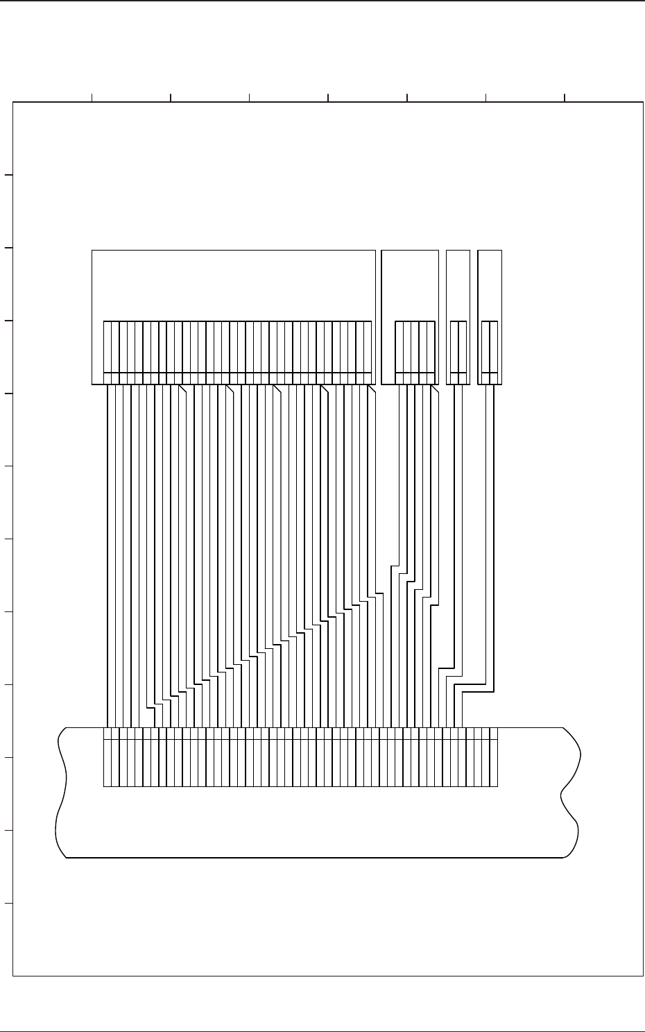
5OM-1610
4-390911-001-(M913WR---0004)
Recognition Connection Diagram 4
E194(1)
E193(1)
E192(1)
E191(1)
Standard Mark Lighting 1B
Standard Mark Lighting 1A
Component Recognition
Coaxial Lighting 1
Component Recognition
Ring Lighting 1
U95
Lighting Control Board
CN5
X6704
X6703
X6702
X6701
X9505
Standard Mark Lighting(Rear)
Standard Mark Lighting(Front)
+48V
+48V
1
2
+48V
Coaxial Lighting (Right)
Coaxial Lighting (Front)
Coaxial Lighting (Left)
Coaxial Lighting (Rear)
+48V
+48V
BGA Upper (Right)
BGA Upper (Front)
BGA Upper (Left)
BGA Upper (Rear)
BGA Lower (Right)
BGA Lower (Front)
BGA Lower (Left)
BGA Lower (Rear)
+48V
Front Lighting Lower (Right)
Front Lighting Lower (Front)
Front Lighting Lower (Left)
Front Lighting Lower (Rear)
+48V
Front Lighting Center (Right)
Front Lighting Center (Front)
Front Lighting Center (Left)
Front Lighting Center (Rear)
+48V
Front Lighting Upper (Right)
Front Lighting Upper (Front)
Front Lighting Upper (Left)
Front Lighting Upper (Rear)
1
2
5
4
3
2
1
+48V
Back Lighting (Front Right)
Back Lighting (Front Left)
Back Lighting (Rear Left)
Back Lighting (Rear Right)
30
29
28
27
26
25
24
23
22
21
20
19
18
17
16
15
14
1
3
12
11
10
9
8
7
6
5
4
3
2
1
GND
+48V
NC
NC
+48V
OUT-30 Standard Mark (Rear)
+48V
OUT-29 Standard Mark (Front)
OUT-28 BGA Lower (Right)
OUT-27 BGA Lower (Front)
OUT-26 BGA Lower (Left)
+48V
+48V
OUT-25 BGA Lower (Rear)
OUT-24 BGA Upper (Right)
OUT-23 BGA Upper (Front)
OUT-22 BGA Upper (Left)
+48V
+48V
OUT-21 BGA Upper (Rear)
+48V
+48 V
OUT-20 Coaxial (Right)
OUT-19 Coaxial (Front)
OUT-18 Coaxial (Left)
OUT-17 Coaxial (Rear)
+48V
+48V
OUT-16 Front Lighting Lower (Right)
OUT-15 Front Lighting Lower (Front)
OUT-14 Front Lighting Lower (Left)
OUT-13 Front Lighting Lower (Rear)
+48V
+48V
OUT-12 Front Lighting Center (Right)
OUT-11 Front Lighting Center (Front)
OUT-10 Front Lighting Center (Left)
OUT-9 Front Lighting Center (Rear)
+48V
+48V
OUT-8 Front Lighting Upper (Right)
OUT-7 Front Lighting Upper (Front)
OUT-6 Front Lighting Upper (Left)
OUT-5 Front Lighting Upper (Rear)
NC
+48V
OUT-4 Back Lighting (Front Right)
OUT-3 Back Lighting (Front Left)
OUT-2 Back Lighting (Rear Left)
OUT-1 Back Lighting (Rear Right)
42
50
49
48
47
46
45
44
43
41
40
39
38
37
36
35
34
33
32
31
30
29
28
27
26
25
24
23
22
21
20
19
18
17
16
15
14
1
3
12
11
10
9
8
7
6
5
4
3
2
1
1
2 3 4 5 6 7 8 9 10 11 12
A
B
C
D
E
F
G
H