5OM-1626-001_w.pdf - 第65页
5OM-1610 1-12 Pneumatic and Mounting Diagrams 091 1-001-(309190800G) High Speed Nozzle Stocker (Mounting Diagram) 9 4 5 6 No. Name Q’ty No. Name Q’ty No. Name Q’ty No. Name Q’ty 4 Solenoid V alve 1 5 Cylinder 1 6 Cylinde…
5OM-1610
1-11
Pneumatic and Mounting Diagrams
0911-001-(309190800G)
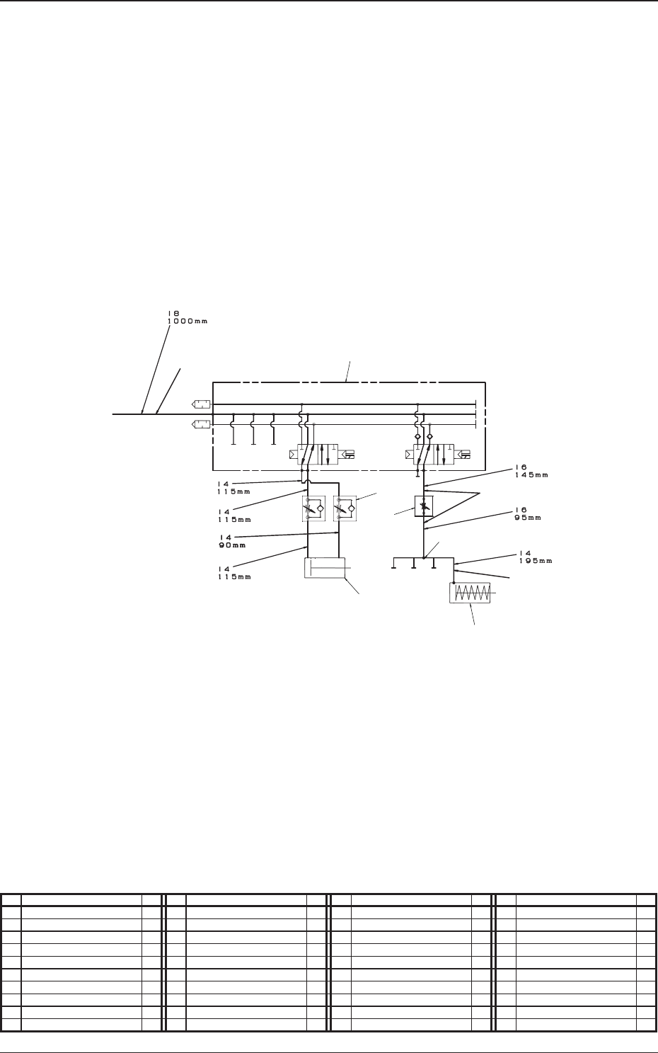
High Speed Nozzle Stocker (Pneumatic Diagram)
7
8
4
5
6
2
3
9
1
From Main Body
Stocker 1 U/D
Shutter 1 Open / Close
No. Name Q’ty No. Name Q’ty No. Name Q’ty No. Name Q’ty
1 Tube
φ
8 1
2 Tube
φ
6 1
3 Tube
φ
4 1
4 Solenoid Valve 1
5 Cylinder 1
6 Cylinder 1
7 Speed Controller 2
8 Needle 1
9 Union Y 1
5OM-1610
1-12
Pneumatic and Mounting Diagrams
0911-001-(309190800G)
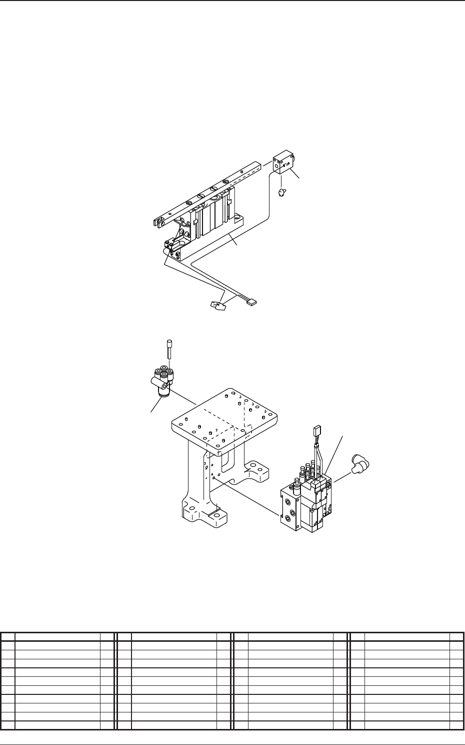
High Speed Nozzle Stocker (Mounting Diagram)
9
4
5
6
No. Name Q’ty No. Name Q’ty No. Name Q’ty No. Name Q’ty
4 Solenoid Valve 1
5 Cylinder 1
6 Cylinder 1
9 Union Y
5OM-1610
1-13
Pneumatic and Mounting Diagrams
0911-001-(3092904100)
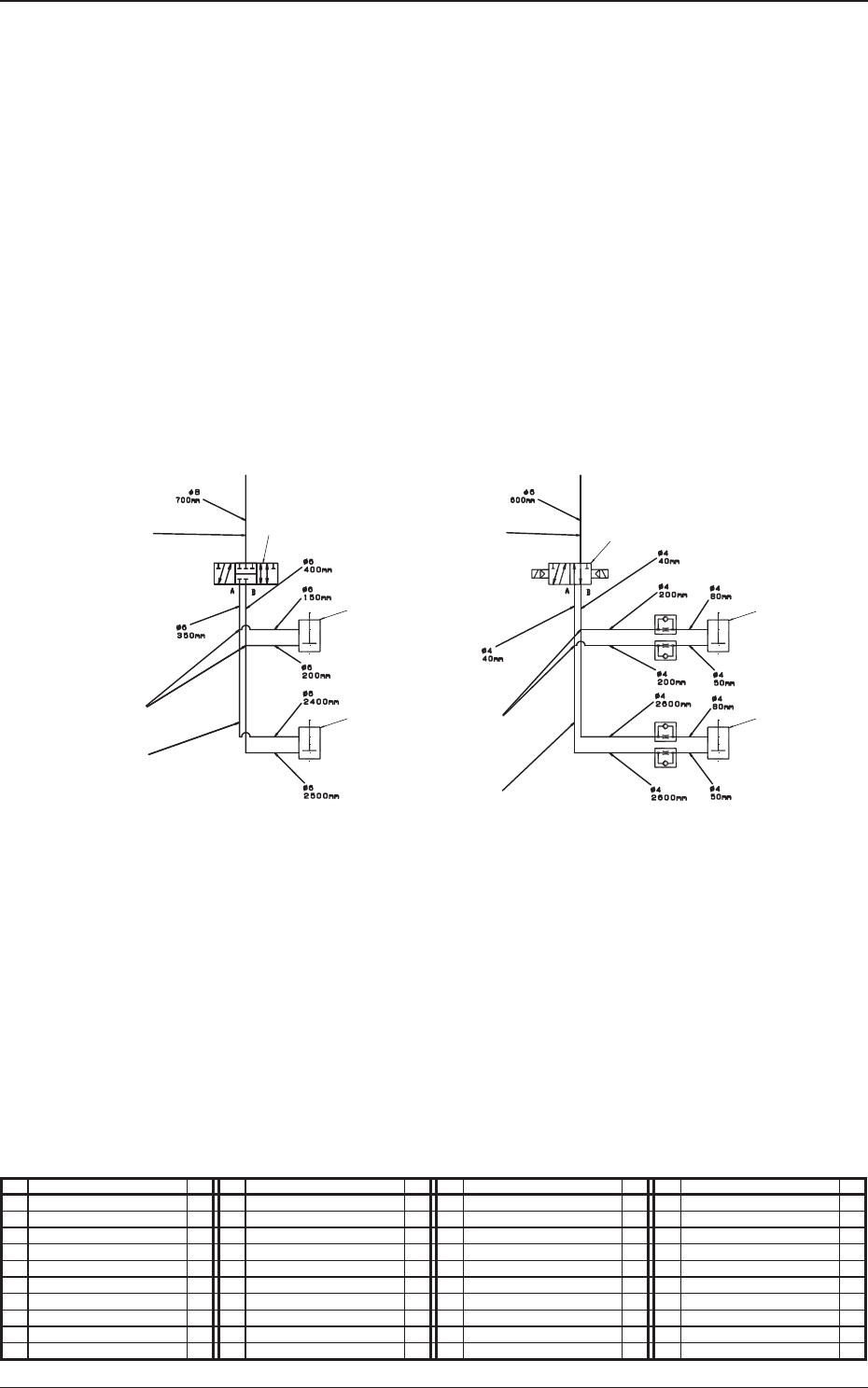
Positioning Unit (Pneumatic Diagram)
2
1
3
5
4
1
Positioning U/D Positioning Unit Lowering Prevention
10
10
9
7
8
9
Right Side Cylinder
Left Side Cylinder
Left Side Cylinder
Right Side Cylinder
From Main Body From Main Body
No. Name Q’ty No. Name Q’ty No. Name Q’ty No. Name Q’ty
1 Tube
φ
6 1
2 Tube
φ
8 1
3 Union Y 2
4 Union Y 2
5 Tube
φ
4 1
7 Solenoid Valve 1
8 Solenoid Valve 1
9 Cylinder 2
10 Cylinder 2