5OM-1626-001_w.pdf - 第71页
5OM-1610 1-18 Pneumatic and Mounting Diagrams 091 1-001- Multi Function Head Unit (Mounting Diagram) No. Name Q’ty No. Name Q’ty No. Name Q’ty No. Name Q’ty 1 Tube φ 6 1 1 1 V acuum Sensor 3 2 Tube φ 6 1 12 Vacuum Filter…
5OM-1610
1-17
Pneumatic and Mounting Diagrams
0911-001-(2091603G00)
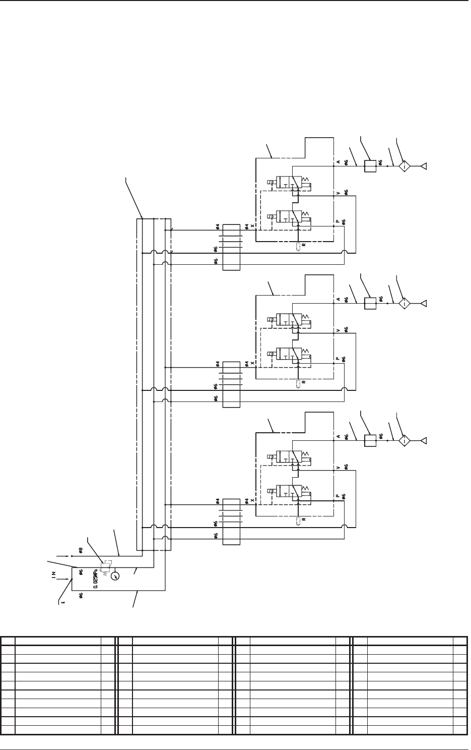
Multi Function Head Unit (Pneumatic Diagram)
No. Name Q’ty No. Name Q’ty No. Name Q’ty No. Name Q’ty
1 Tube
φ
6 1 11 Vacuum Sensor 3
2 Tube
φ
6 1 12 Vacuum Filter 3
3 Tube
φ
6 1
4 Tube
φ
6 1
5 Tube
φ
6 1
6 Tube
φ
8 1
7 Regulater 1
8 Union Y 1
9 Manifold Unit 1
10 Solenoid Valve Unit 3
5
5
6
9
2
11
10
10
10
1
2
11
12
12
1
2
11
12
1
7
8
3
Nozzle 1
Nozzle 2
Setup
Vacuum
Air
Nozzle 3
5OM-1610
1-18
Pneumatic and Mounting Diagrams
0911-001-
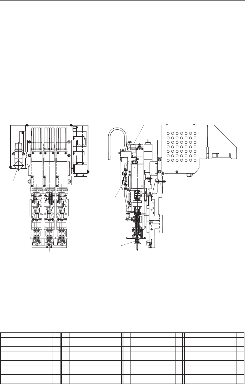
Multi Function Head Unit (Mounting Diagram)
No. Name Q’ty No. Name Q’ty No. Name Q’ty No. Name Q’ty
1 Tube
φ
6 1 11 Vacuum Sensor 3
2 Tube
φ
6 1 12 Vacuum Filter 3
3 Tube
φ
6 1
4 Tube
φ
6 1
5 Tube
φ
6 1
6 Tube
φ
8 1
7 Regulater 1
8 Union Y 1
9 Manifold Unit 1
10 Solenoid Valve Unit 3
NOZZLE1 NOZZLE2 NOZZLE3
7
10
11
12
5OM-1610
1-19
Pneumatic and Mounting Diagrams
0911-001-(3091908303)
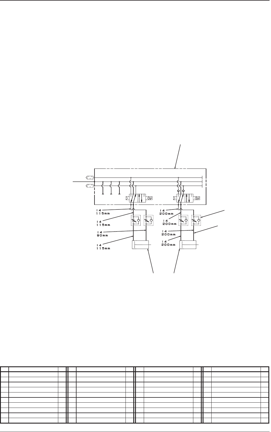
Multi Function Nozzle Stocker (Pneumatic Diagram)
No. Name Q’ty No. Name Q’ty No. Name Q’ty No. Name Q’ty
1 Tube
φ
4 1
2 Solenoid Valve 1
3 Speed Controller 2
4 Cylinder 1
5 Cylinder 1
4
5
2
3
1
Shutter 1 Open / Close
Stocker 1 U/O
From the Inside of Whole Base