00194329-03.pdf - 第146页
Replacement instructions - Gantry c able and hose carrier SIPLACE HS / S / F 01/2007 Edition 146 : Run the compressed air ho ses through the head board mount. : Attach the compressed air hoses fr om the cable and hose ca…
Replacement instructions - Gantry cable and hose carrier SIPLACE HS / S / F
01/2007 Edition
145
2.2.7.5 Installing the cable and hose carrier
: Place the cable and hose carrier in the machine so that it is not damaged.
Fix it temporarily in position at suitable points.
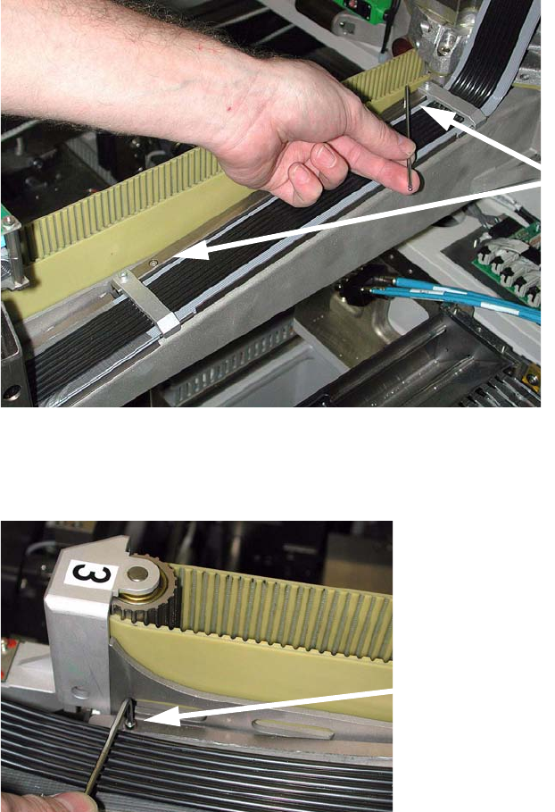
: Screw the plate to which the cable and hose carrier is attached to the gantry arm.
2
2
: Screw on the cable and hose carrier beside the idler pulley (1 screw).
2
2
2
2
2
2 screws
Tighten the screw
Replacement instructions - Gantry cable and hose carrier SIPLACE HS / S / F
01/2007 Edition
146
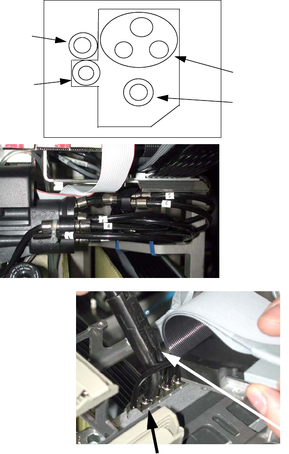
: Run the compressed air hoses through the head board mount.
: Attach the compressed air hoses from the cable and hose carrier to the vacuum generator (HS-
50) or to the clamp strip (HS-60).
2
If you stand beside the machine and look along the gantry towards the X-axis motor, you will see
that hose connections 1 - 7 run from right to left, i.e. the hoses are run in the same order that they
lie on the gantry arm, and do not turn at all. 2
3
4
1
2+5
6
7
Vacuum for holding circuit
Vacuum for placement
circuit
Reserved
Forced air
for rejecting &
placement
3
4
1
2+5
6
7
Reserved
HS-50
Attach the hoses (HS-60)
HS-60
7
Looking
towards the
X-axis motor
Replacement instructions - Gantry cable and hose carrier SIPLACE HS / S / F
01/2007 Edition
147
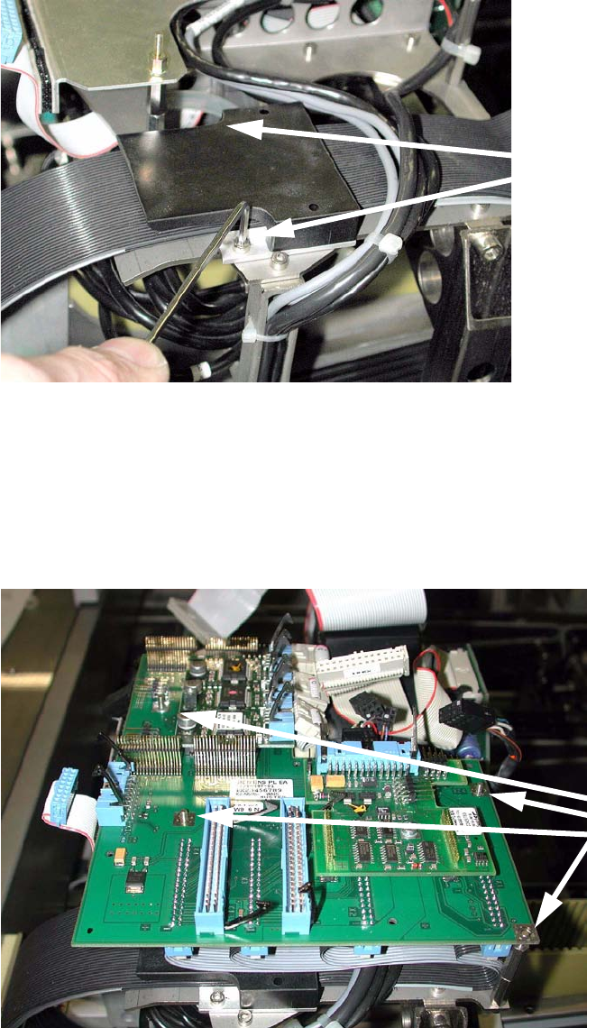
: Fix the ribbon cable clamp to the placement head (2 screws).
2
2
: Plug in the ribbon cable connectors on the underside of the head board.
: Fit the head board and screw it in place.
Make sure that the ribbon cables run correctly beneath the board
(see also next page).
2
2
2 screws
4 screws