00194329-03.pdf - 第160页
Replacement instructions - Gantry c able and hose carrier SIPLACE HS / S / F 01/2007 Edition 160 2 2 2 2 2 2 2 2 2 1 Y cable and hose carrier mou nt S-25 HM 2 2 Support for Y cable and ho se carrier S-25 HM 2 3 Support Y…
Replacement instructions - Gantry cable and hose carrier SIPLACE HS / S / F
01/2007 Edition
159
2
2
2
2
2
2
2
2
2
2
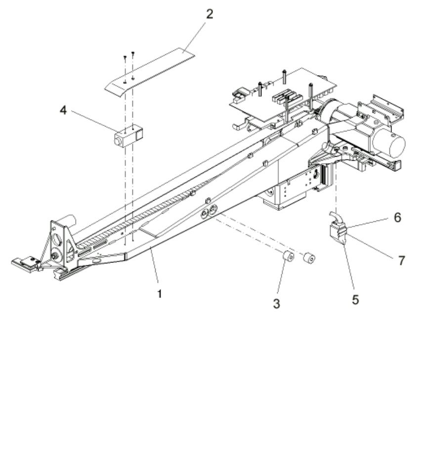
1 Main gantry S-27
2 Guide plate
3 Elastomeric spring 20*8.5*16 (90 SHORE A)
4 Distance light barrier
5 Scanning head, digital, Y axis
6 Sensor: Y axis end position
7 Sensor: Y axis end position
Replacement instructions - Gantry cable and hose carrier SIPLACE HS / S / F
01/2007 Edition
160
2
2
2
2
2
2
2
2
2
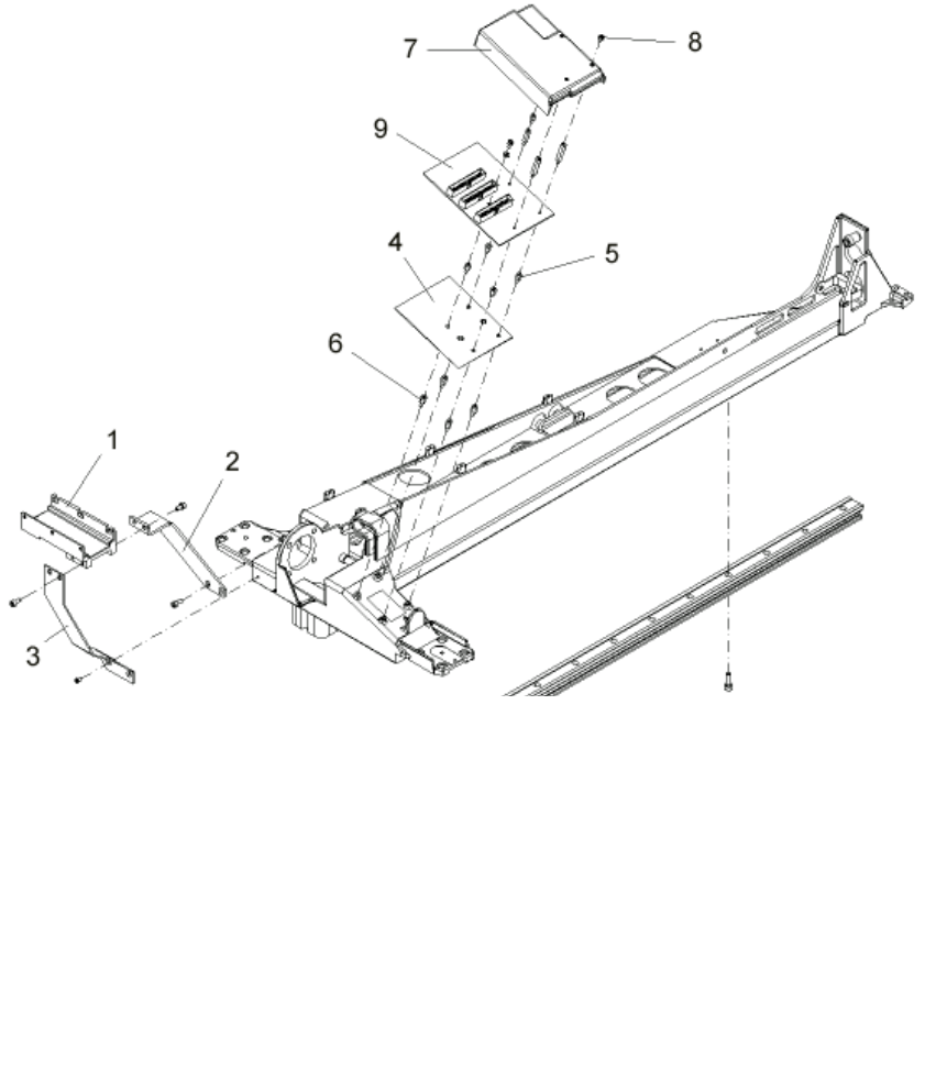
1 Y cable and hose carrier mount S-25 HM 2
2 Support for Y cable and hose carrier S-25 HM 2
3 Support Y carrier S-25 HM 2
4 PCB guard
5 Spacer bolt M3*7 IA 6K/T5.5 ST galvanized
6 Spacer bolt M3*10 IA 6K/T5.5 brass
7 PCB cover
8 Fillister head screw M3*5 DIN 912
9 Large axis conversion board S-27 HM
Replacement instructions - Gantry cable and hose carrier SIPLACE HS / S / F
01/2007 Edition
161
These instructions apply to S and F machines from S-20 / F4 onwards.
Replacement of the cable and hose carrier is shown with reference to the SIPLACE S-27 HM. Re-
placement on the other types of machine is carried out in the same way. 2
2.2.9 Dismantling the cable and hose carrier
2
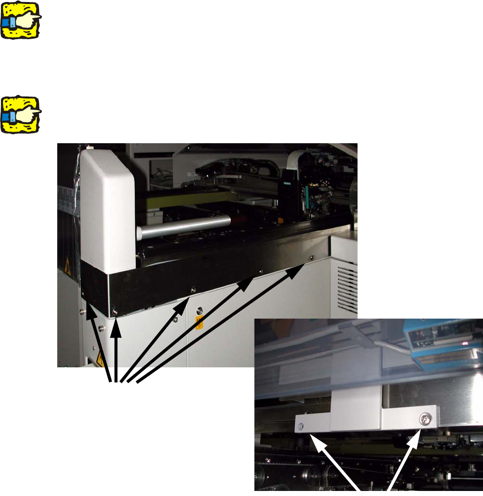
It is absolutely essential to remove the protective covers in order to replace the cable and hose
carrier. 2
2
: To remove the design panels, loosen the screws on the panels. To do this, loosen a screw on
each arched cross-piece on the output side.
2
Only loosen one screw on each cross-piece. The arched cross-piece is very heavy and might oth-
erwise fall off and cause damage or injury. 2
2
2
Screws
Screws on arched cross-piece.