00194329-03.pdf - 第154页
Replacement instructions - Gantry c able and hose carrier SIPLACE HS / S / F 01/2007 Edition 154 : At gantry 1 and 3, wind up the spiral hose to prevent the hoses rubbing against the gantry frame. This is not nece ssary …
Replacement instructions - Gantry cable and hose carrier SIPLACE HS / S / F
01/2007 Edition
153
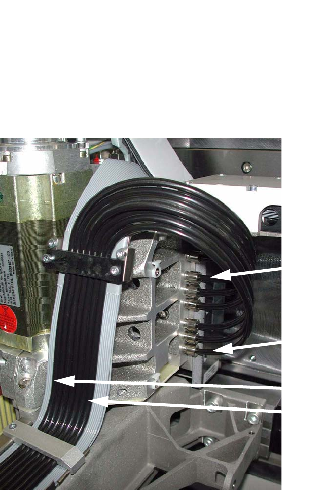
: Run the compressed air hose following the arc, and attach them to the connections on the gan-
try in the following arrangement:
2
When you attach the hose, there is a slight resistance that must be overcome before the hose is
seated correctly. 2
2
2
2
2
2
2
Compressed air hoses
No. 1 - 7 from right to left
Compressed air con-
nections
No. 1 - 7 from top to bottom
Hose 1, connection 1
Hose 1
Hose 7, connection 7
Hose 7
Replacement instructions - Gantry cable and hose carrier SIPLACE HS / S / F
01/2007 Edition
154
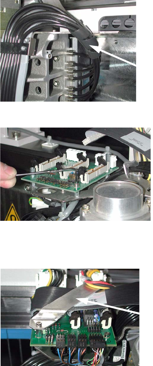
: At gantry 1 and 3, wind up the spiral hose to prevent the hoses rubbing against the gantry
frame. This is not necessary on gantry 2 and 4.
2
: Attach the X/Y-axis distributor board to the mount.
2
: Plug in all cables on the X/Y-axis distributor board.
: HS-50 only:
Screw on the protective plate over the X/Y-axis distributor.
2
Spiral hose
Protective plate
Replacement instructions - Gantry cable and hose carrier SIPLACE HS / S / F
01/2007 Edition
155
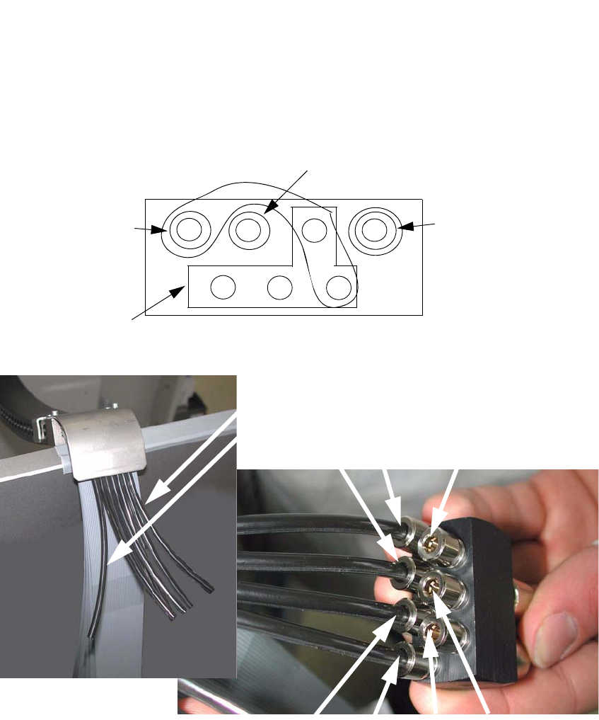
: Attach the hoses to the air distributor in the following arrangement:
Hose 1 is always on the outside (on every gantry) and is attached to the air distributor opposite
the small connection (this connection is always left clear because it is the only one that is di-
rectly visible).
2
2
2
2
Compressed air hose no. 1 - 7
Gantries 1 and 3 from right to left
Gantries 2 and 4 from left to right
3
4
1
2
5
6
7
1
7
On gantry 1 and 3, hoses 1 - 7 run from right to left, on
gantry 2 and 4 they run the opposite way around.
Forced air
for rejecting &
placement
4
Vacuum for hold-
ing circuit
3
1
2
7
6
5
Reserved
Vacuum for placement circuit