TM1467_ReleaseNote_PSC乮Print Stability Control乯-SyringeType-Function.pdf - 第27页
SMT Software Engineeri ng Group IMOperationsYAMAHAMOTORCO. ,LTD. MD OC-SOFT50033 27/30 According to “Fig.7.1 .1 External view”, t he solder supp ly a ction is e xecuted o nly after printing in the …
SMT Software Engineering Group
IMOperationsYAMAHAMOTORCO.,LTD.
MDOC-SOFT50033
26/30
7. Appendix
7.1 Summary of unit
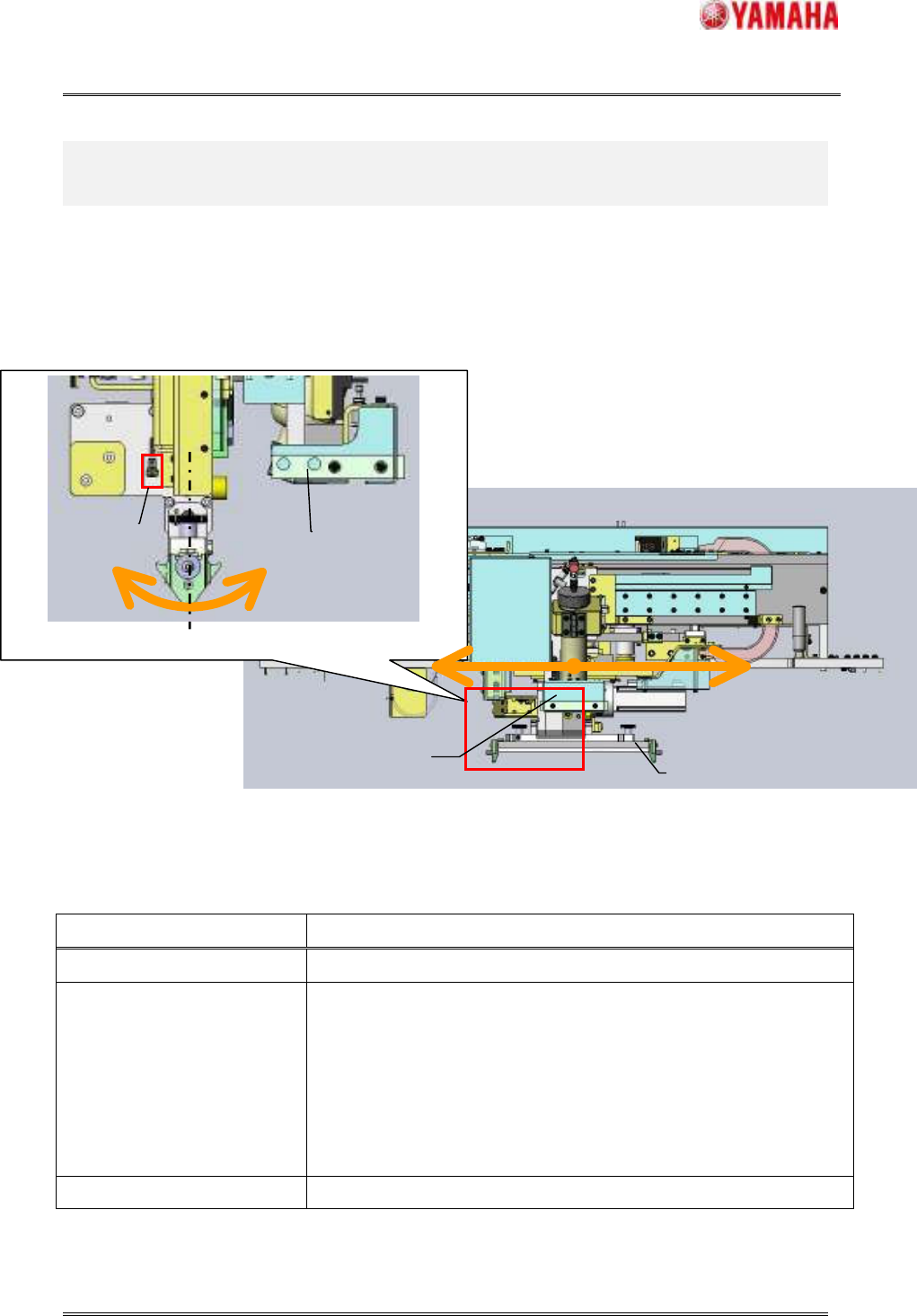
The exclusive units are necessary for PSC function. For example, “Solder supply unit”. The external
view of units and the list of necessary units are as follows.
Fig.7.1.1 External view
Table7.1.2 List of additional unit for PSC function
Item name Content
FX axis This axis is for moving the solder supply unit to X direction.
Solder supply unit This unit is for supplying the solder by blowing solder syringe. And this
is equipped with “Solder cutter” and “Solder empty sensor”.
The “Solder cutter” is for cutting the supplying solder and used to prevent
solder from falling, too.
The “Solder empty sensor” is for detecting the remained level of solder in
syringe.
Solder scan sensor This sensor is for scanning the rolling width.
Left side elevation view (Close-up)
Solder
supply unit
SR axis
FX axis
Squeegee
Solder
supply unit
Elevation view
Solder scan
sensor
SMT Software Engineering Group
IMOperationsYAMAHAMOTORCO.,LTD.
MDOC-SOFT50033
27/30
According to “Fig.7.1.1 External view”, the solder supply action is executed only after printing in the
forward direction. And then, there is a possibility that print cycle time increases when the “Round”
printing is set to board data. Because the solder supply unit supplies the solder in switching the printing
direction.
The solder supply unit is attached in front of squeegee. If the supply action is executed after printing in
the backward direction, there is a possibility that a defective printing is because the solder adhered to the
squeegee may fall onto the hole of mask. So, the solder supply action is executed after printing in the
forward direction only.
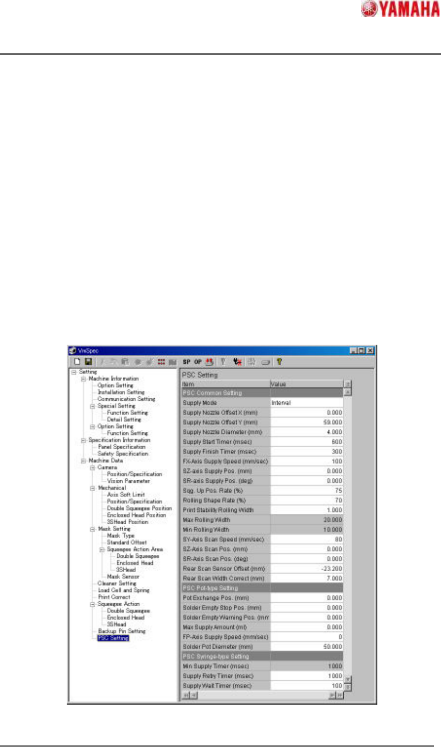
7.2 PSC settings
The detailed setting items for this function are discussed in this section. Basically, you need not change
the following settings.
When this function is enabled in “3.1 Machine settings”, [Setting] – [Machine Data] – [PSC Setting] is
appeared in the tree view.
Fig.7.2.1 PSC setting
SMT Software Engineering Group
IMOperationsYAMAHAMOTORCO.,LTD.
MDOC-SOFT50033
28/30
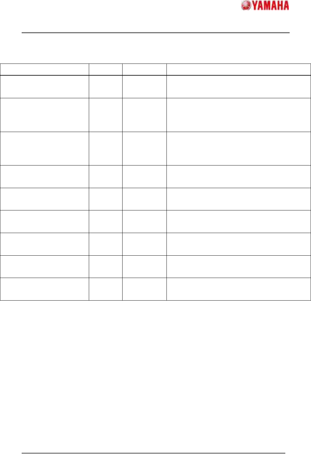
Table7.2.2 Parameters of PSC common setting
Item Initial Input range Content
Supply Mode Interval
Interval/
Feedback
The supply mode is set by this parameter.
Please refer to "4. Details" for details.
Supply Nozzle Offset X (mm) 0.000
-999.999~
999.999
This is supply nozzle mounted offset of X direction
from squeegee center to supply nozzle. Please set an
initial value usually.
Supply Nozzle Offset Y (mm) 59.000
-999.999~
999.999
This is supply nozzle mounted offset of Y direction
from the center of the SR-axis rotation to supply
nozzle. Please set an initial value usually.
Supply Nozzle Diameter (mm) 4.000
0.000~99.999
This parameter is diameter of supply nozzle. This
parameter is used to decide the supply time.
Supply Start Timer (msec) 600
0~9999
This is the time from beginning to blow the syringe to
beginning the FX-axis movement.
Supply Finish Timer (msec) 300
0~9999
This is the time from stopping blowing the syringe to
beginning to cut the supplying solders.
FX-axis Supply Speed
(mm/sec)
100
0~999
This is the movement speed of the FX-axis in
supplying the solders.
SZ-axis Supply Pos. (mm) 0.000
-99.999~
99.999
This is the height of the SZ-axis in supplying the
solders. Please set an initial value usually.
SR-axis Supply Pos. (deg) 0.000
0.000~
180.000
This is the angle of the SR-axis in supplying the
solders. Please set an initial value usually.