OI_WT1_WT1H_supplementary.pdf - 第15页
15 Resetting to factory settings 3 sec When switching on: Press and hold Exit, UP and DOWN for three seconds T ool recognition and overload limiting The WT 1 and WT 1H have automatic tool recognition which assigns the re…
14
2
1
3
Example
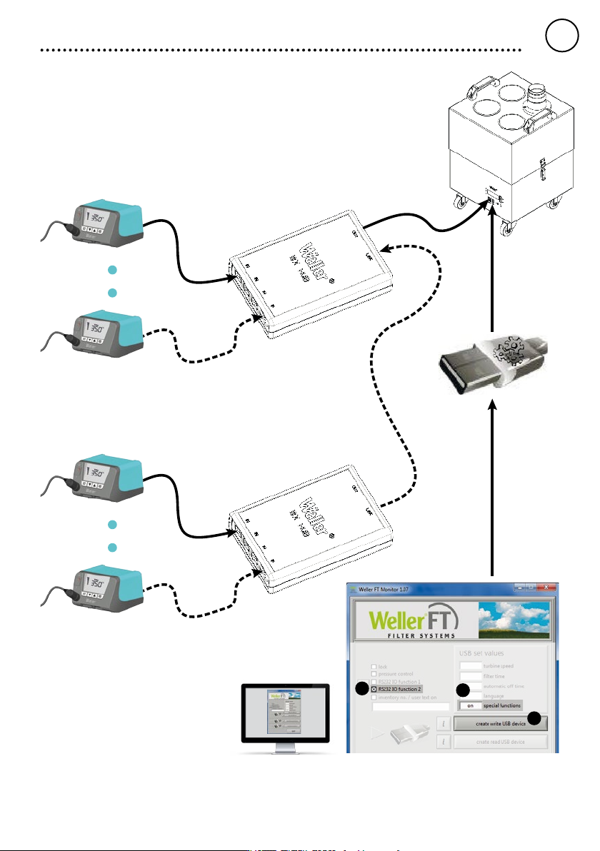
Zero-Smog output conguration
GB
ENGLISH
15
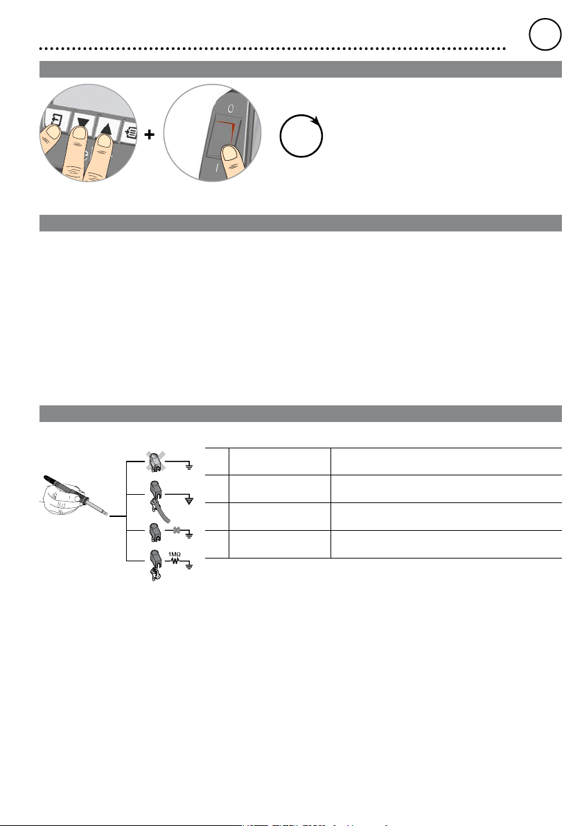
Resetting to factory settings
3
sec
When switching on: Press and hold Exit, UP and DOWN for three seconds
Tool recognition and overload limiting
The WT 1 and WT 1H have automatic tool recognition which assigns the relevant control parameters to the connected tool.
To prevent overloading a station, only compatible tools are supported:
WT 1 max. 90 W:
WSP 80, WP 80, WTP 90, WP 65, WST 82, WSB 80, WHP 80, WTA 50, LR 21, MPR 80, WMP, FE 75
WT 1H max. 150 W (200 W):
WSP 80, WP 80, WTP 90, WP 120, WSP 150, WP 200*,
WP 65, WST 80, WSB 80, WSB 150, WHP 80, WTA 50, LR 21, MPR 80, WMP, FE 75
*Maximum power 150 Watt
Equipotential bonding
a
b
c
d
Four variants are possible by connecting the 3.5 mm jack socket differently:
a Hard-grounded supplied without plug.
b Equipotential bonding with plug, equaliser at centre contact.
c Floating with plug
d Soft-grounded with plug and soldered resistor. Grounded through
selected resistor.
GB
ENGLISH
16
Soldering and desoldering
Carry out soldering work as directed in the operating instructions of your connected soldering tool.
Handling the soldering tips
• Coat the selective and tinnable soldering tip with solder
when heating it up for the rst time. This removes oxide
coatings which have formed during storage and impurities
from the soldering tip.
• Make sure that the soldering tip is well coated with solder
during breaks between soldering work and prior to storage
of the device.
• Do not use aggressive uxing agents.
• Always make sure that the soldering tips are tted properly.
• Select as low a working temperature as possible.
• Select the largest possible soldering tip shape for the
application.
Rule of thumb: the soldering tip should be roughly as large
as the soldering pad.
• Coat the soldering tip well with solder to ensure that there
is efcient heat transfer between the soldering tip and the
soldering area.
• Prior to extended breaks between soldering work, switch
off the soldering system or use the Weller function to
reduce the temperature when the soldering equipment is
not in use.
• Coat the tip with solder prior to storage if you do not intend
to use the soldering iron for an extended period of time.
• Apply solder directly to the soldering area, not to the
soldering tip.
• Change the soldering tips using the designated tool.
• Do not apply mechanical force to the soldering tip.
Notice
The control units have been adapted to hold a
medium-sized soldering tip. Discrepancies may occur if
the tip is changed or a different shaped tip is used.
Error messages and error clearance
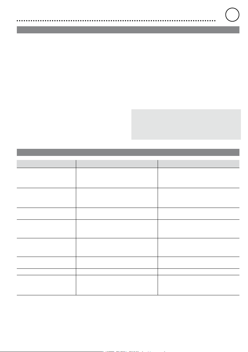
Message/symptom Possible cause Remedial measures
• Display: „- - - • Tool has not been detected
• Tool defective
• Tool not compatible
• Check connection of tool to device
• Check connected tool
• No display function (display
OFF)
• No mains supply voltage • Turn on mains power switch
• Check mains supply voltage
• Check device fuse
• OFF • Station is on standby or in OFF mode • Reactive the soldering tool using the UP
or DOWN buttons
• Tool remains cold • Station is on standby or in OFF mode • Move the gun
• Reactive the soldering tool using the UP
or DOWN buttons
• Temperature shown in the
display
• Tool remains cold
• Heating defective • Check/replace the soldering tool
• Station is not operating as it
usually does
• Parameters set incorrectly • Reset the station to the factory settings
• Settings cannot be changed • Station locked • Unlocking the station
• Zero Smog is not running • No mains supply voltage
• No signal detected
• Check the mains power supply
• Check the interface wiring
• Check the interface settings
GB
ENGLISH