00195679-02_AI_XPS_DE+EN.pdf - 第67页
9 Assembly Instructions 3 Preliminary Work on the SIPLACE X-Series SIPLACE X-Series Productivity Shuttle T ype I/II 3.1 Preparation for Installing the XPL 3 Preliminary W ork on the SIPLACE X-Series T o install the SIPLA…

2 Operating Safety Assembly Instructions
SIPLACE X-Series Productivity Shuttle Type I/II
8
WARNING
You must follow the sequence of the individual assembly steps in order to avoid injuries and/or
property damage.
Do not operate the XPS outside the SIPLACE placement system.
Hands may be crushed in the traversing range of the shuttle.
Prior to commissioning the XPS, always ensure that all coverings have been reattached and
safety devices are active.
Any disconnected ground connection for the coverings must be reconnected.

9
Assembly Instructions 3 Preliminary Work on the SIPLACE X-Series
SIPLACE X-Series Productivity Shuttle Type I/II 3.1 Preparation for Installing the XPL
3 Preliminary Work on the SIPLACE
X-Series
To install the SIPLACE X-Series Productivity Lane (XPL) in the SIPLACE X-Series, the following
preliminary work must be carried out on the placement system.
NOTE
Always refer to the operating and assembly instructions of the placement system in this regard.
1. Position the fixed walls of the SIPLACE X-Series at the outside-outside.
2. Set the transport width of the SIPLACE X-Series to 100 mm.
3. Switch off the SIPLACE X-Series at the main switch, and unplug and disconnect the power
supply.
4. Remove the covers at the inlet and outlet of the placement system. This will enable easier
installation of the XPL later on.
5. Remove the lifting table plates in placement area 2.
6. Remove the cover of the main distributor of the conveyor control.
3.1 Preparation for Installing the XPL
A limit switch of the XPL must be connected to the main distributor of the conveyor control of the
SIPLACE X-Series. For this purpose, the relevant cable must be connected and routed as follows.
3 Preliminary Work on the SIPLACE X-Series Assembly Instructions
3.2 Routing and Connection of the Limit Switch Cable SIPLACE X-Series Productivity Shuttle Type I/II
10
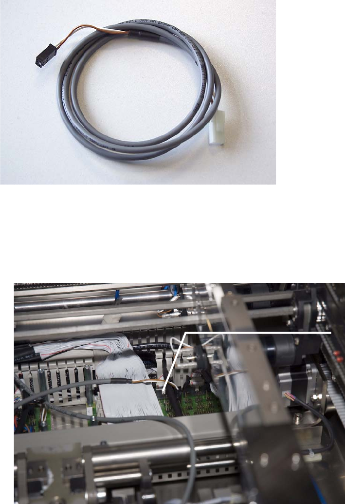
3.1.1 Required Part
Cable/limit switch for XPL, Part number: 03065827-01
3.2 Routing and Connection of the Limit Switch Cable
7. Insert the cable for the SIPLACE X-Series onto the X7KU contact of the conveyor control.
X7KU transport control