00195679-02_AI_XPS_DE+EN.pdf - 第72页
4 Installation of the XPL Assembly Instructions 4.1 Mechanical Installation SIPLACE X- Series Productivity Shuttle T ype I/II 14 3. T ake XPL Part 1, which can be recognized by the aluminum strips at the in let. Introduc…
13
Assembly Instructions 4 Installation of the XPL
SIPLACE X-Series Productivity Shuttle Type I/II 4.1 Mechanical Installation
4 Installation of the XPL
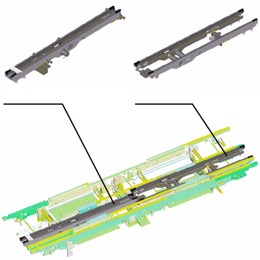
The XPL consists of two parts that are screwed together after installation in the placement system.
4.1 Mechanical Installation
1. Make sure that the width of the SIPLACE X-Series is adjusted to 100 mm.
2. In the as-delivered condition, both parts of the XPL are secured at their minimum width with
cable ties. Leave the cable ties until the parts are installed.
XPL Part 1 - Inlet XPL Part 2 - Outlet
4 Installation of the XPL Assembly Instructions
4.1 Mechanical Installation SIPLACE X-Series Productivity Shuttle Type I/II
14
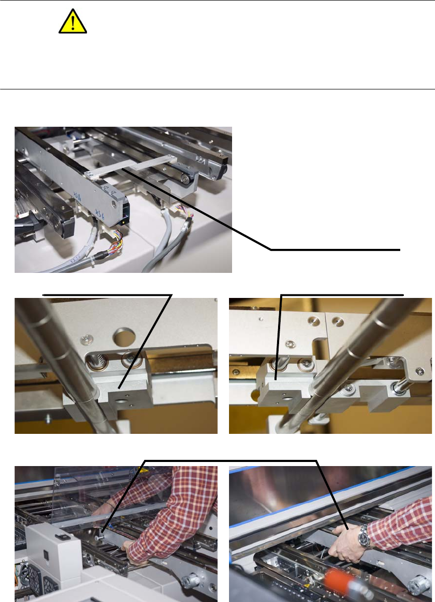
3. Take XPL Part 1, which can be recognized by the aluminum strips at the inlet. Introduce it into
the placement system from the front so that it contacts the shaft bearings on the guide shafts
(∅
25 mm) of the SIPLACE.
CAUTION
The XPL is mounted on the conveyor below the Y-axis of the SIPLACE. Both the locating
conveyor for the transport walls and the Y-scale on the machine frames are located here.
Make certain that you do not damage these parts when inserting the XPL.
Aluminum strips at the inlet
of the first part of the XPL.
Shaft encoder in the center
of the connected XPL.
Shaft encoder at the inlet
and outlet of the XPL.
Introducing the XPL into the placement
system from the inlet side.
15
Assembly Instructions 4 Installation of the XPL
SIPLACE X-Series Productivity Shuttle Type I/II 4.1 Mechanical Installation
4. Mount the second part of the XPL in the placement system accordingly, but from the outlet
side.
5. Now, remove the cable ties holding the XPL parts together.
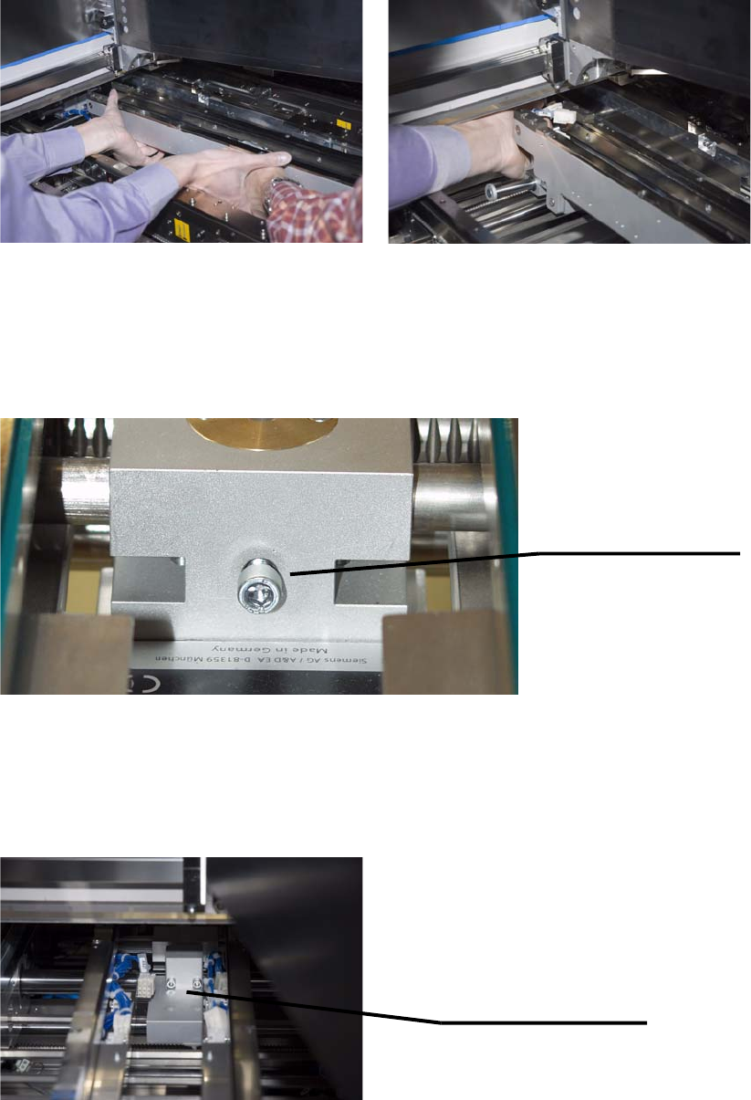
6. Loosen the knurled-head or cylinder-head screw and push open the width of the XPL to the
maximum width (to the stop). Re-tighten the knurled-head or cylinder-head screw to secure
this setting.
7. Both parts of the XPL must now be screwed together in the center. You need two hexagon
socket head cap screws DIN 912 M5x40 and two washers DIN
433-5,3 for this purpose.
Tighten the screws only partially so that the XPL can still be shifted laterally for alignment
purposes.
Setscrew for the width
adjustment of the XPL.
(knurled-head or
cylinder-head screw)
Using the two hexagon
socket head cap screws
DIN 912 M5x40 and washers
DIN 433-5,3, screw the two
XPL parts together.