00195679-02_AI_XPS_DE+EN.pdf - 第91页
33 Assembly Instructions 6 Making the Interface Connections SIPLACE X-Series Productivity Shuttle T ype I/II 6 Making the Interface Connections For one thing, the interface co nnection from the XPS to the pl acement syst…
5 Mounting the XPS Assembly Instructions
5.6 Safety Cover SIPLACE X-Series Productivity Shuttle Type I/II
32
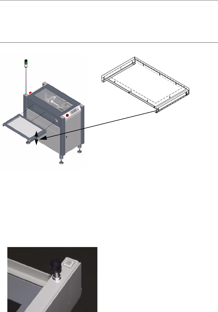
5.6.2 Installation
NOTE 5
The safety cover must not be installed as a self-supporting cover under any circumstances. It's
design calls for the cover to rest on the adjacent conveyor module.
If this is not possible, this cover is not suitable and must be replaced by a special cover.
Figure 5 - 5 Installing the safety cover
1. The safety cover is attached to the XPS using three hexagon socket head cap screws M4x12
DIN
912. The screws are included with the cover.
2. The side parts of the cover are height-adjustable. The setting range is 24 mm. This adjustment
must be used to ensure that the cover rests on the conveyor belt.
3. If 24 mm is not sufficient, the spacing bolts shown in the figure can be used in the M4 thread
on the bottom of the side parts. These parts are not included in the scope of delivery.
33
Assembly Instructions 6 Making the Interface Connections
SIPLACE X-Series Productivity Shuttle Type I/II
6 Making the Interface Connections
For one thing, the interface connection from the XPS to the placement system and from the XPS
to the XPS must be made.
NOTE
Note the interface description in Chapter Interface Description and the circuit diagram
documentation for the XPS.
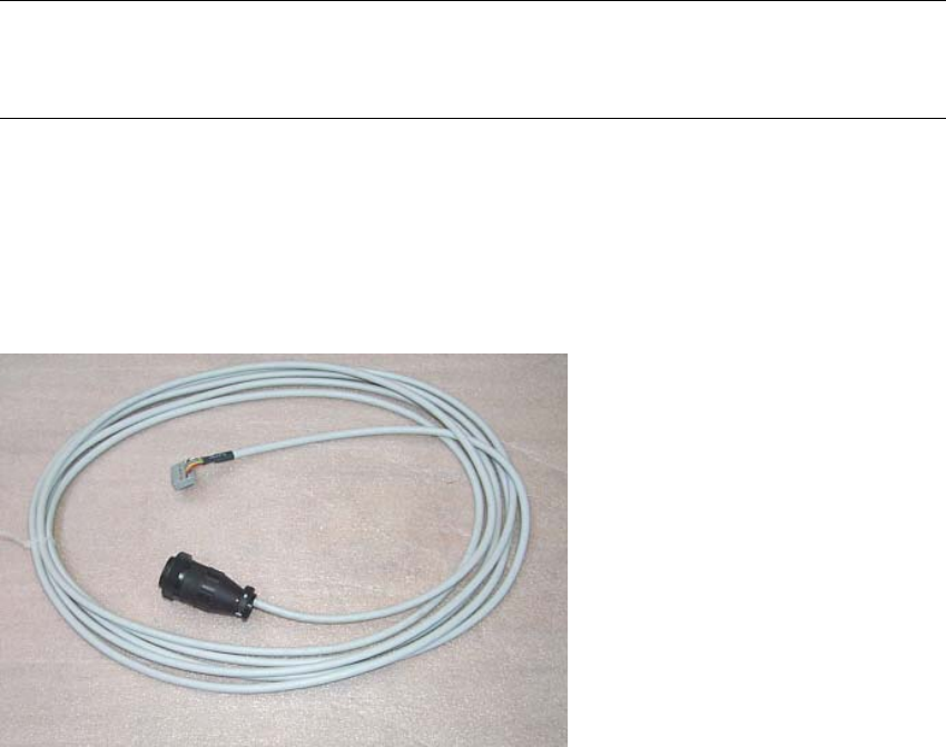
The following SMEMA interface cables are included in the delivery:
3x 00353086-02 l = 5 m, 1x socket connector 16-pin, 1x CPC
3x 00365032-02 l = 5 m, 1x socket connector 16-pin, 1x CPC
6 Making the Interface Connections Assembly Instructions
6.1 Connection to the SIPLACE Placement System SIPLACE X-Series Productivity Shuttle Type I/II
34
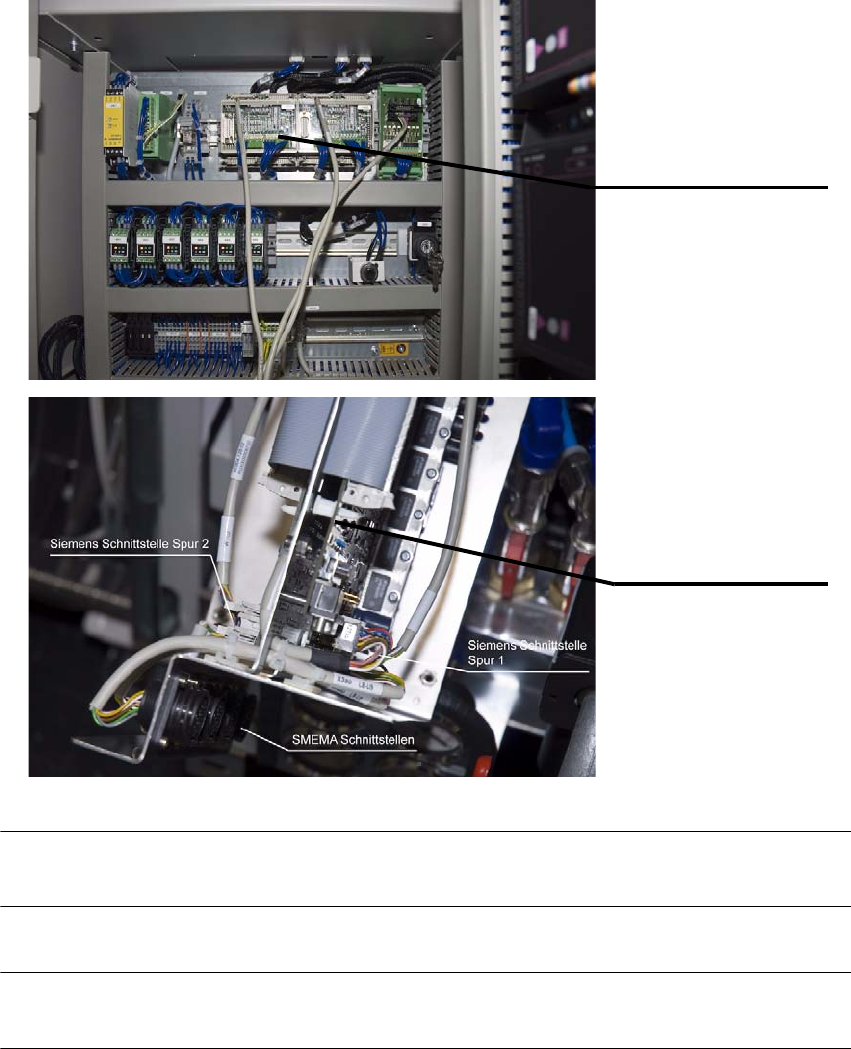
6.1 Connection to the SIPLACE Placement System
1. The SMEMA connection is made from the AMI module of the XPS to the interface connection
of the placement system.
NOTE
Refer to the circuit diagram for the XPS for the terminal markings.
NOTE
Route the cables on or under the machine to prevent them from posing a tripping hazard.
AMI 3.x - Tracks 1 and 2
Interface connections on
the placement system