00195679-02_AI_XPS_DE+EN.pdf - 第74页
4 Installation of the XPL Assembly Instructions 4.2 Making Electrical Connections SIPLACE X-Series Productivity Shuttle T ype I/II 16 4.2 Making Electrical Connections 1. Join together the connectors of the two part s of…
15
Assembly Instructions 4 Installation of the XPL
SIPLACE X-Series Productivity Shuttle Type I/II 4.1 Mechanical Installation
4. Mount the second part of the XPL in the placement system accordingly, but from the outlet
side.
5. Now, remove the cable ties holding the XPL parts together.
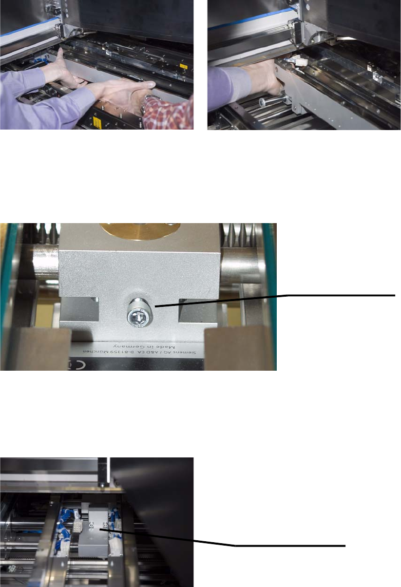
6. Loosen the knurled-head or cylinder-head screw and push open the width of the XPL to the
maximum width (to the stop). Re-tighten the knurled-head or cylinder-head screw to secure
this setting.
7. Both parts of the XPL must now be screwed together in the center. You need two hexagon
socket head cap screws DIN 912 M5x40 and two washers DIN
433-5,3 for this purpose.
Tighten the screws only partially so that the XPL can still be shifted laterally for alignment
purposes.
Setscrew for the width
adjustment of the XPL.
(knurled-head or
cylinder-head screw)
Using the two hexagon
socket head cap screws
DIN 912 M5x40 and washers
DIN 433-5,3, screw the two
XPL parts together.
4 Installation of the XPL Assembly Instructions
4.2 Making Electrical Connections SIPLACE X-Series Productivity Shuttle Type I/II
16
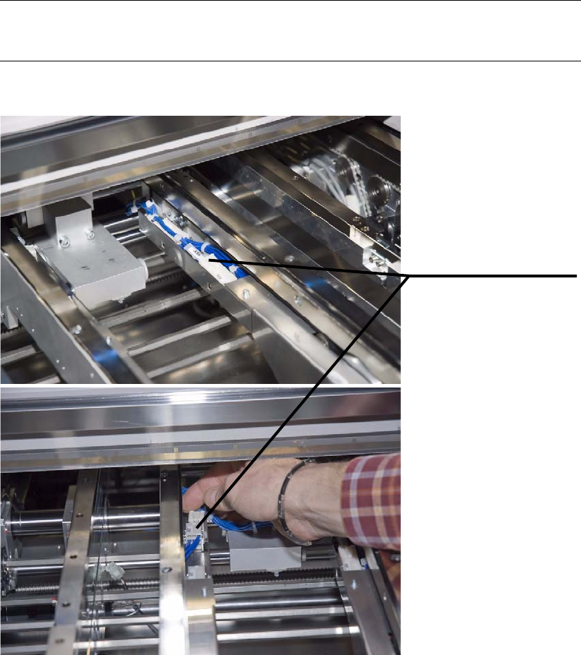
4.2 Making Electrical Connections
1. Join together the connectors of the two parts of the XPL. These cannot be interchanged
because the different cable lengths mean that only two connector pairs per side fit each other.
NOTE
Make sure that the cables do not protrude the duct.
Join together the
appropriate connectors
on both sides of the XPL.
17
Assembly Instructions 4 Installation of the XPL
SIPLACE X-Series Productivity Shuttle Type I/II 4.3 Aligning the XPL
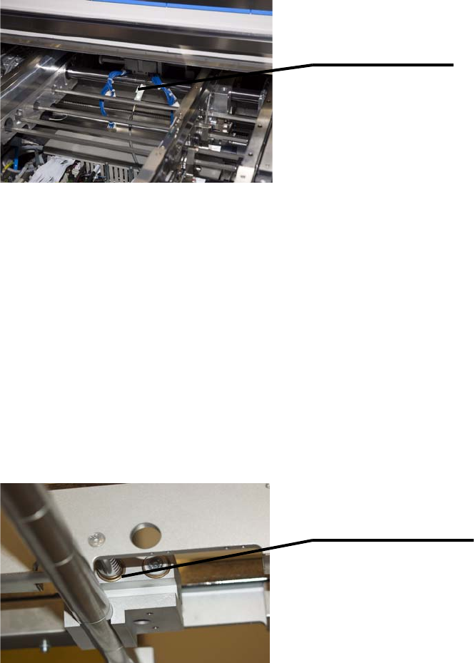
2. Connect the limit switch cable, which is already installed in the placement system, to the XPL.
4.3 Aligning the XPL
1. Switch on the SIPLACE X-Series again at the main switch.
NOTE
For better accessibility, the walls should be in position 268 and the machine should be
operated in the “Transport walls outside” or “Fixed rail outside” transport mode!
2. Adjust the width of both transport tracks of the SIPLACE X-Series to 152 mm.
3. Push the two transport walls of the XPL apart up to the stop. Make sure that all three adjusting
units of the XPL are moved the maximum distance apart!
Connect limit switch
cable to XPL.
Adjusting unit of XPL