00195679-02_AI_XPS_DE+EN.pdf - 第92页
6 Making the Interface Connections Assembly Instructions 6.1 Connection to the SIPLACE Placement System SIPLACE X-Series Productivity Shuttle T ype I/II 34 6.1 Connection to the SIPLACE Placement System 1. The SMEMA conn…
33
Assembly Instructions 6 Making the Interface Connections
SIPLACE X-Series Productivity Shuttle Type I/II
6 Making the Interface Connections
For one thing, the interface connection from the XPS to the placement system and from the XPS
to the XPS must be made.
NOTE
Note the interface description in Chapter Interface Description and the circuit diagram
documentation for the XPS.
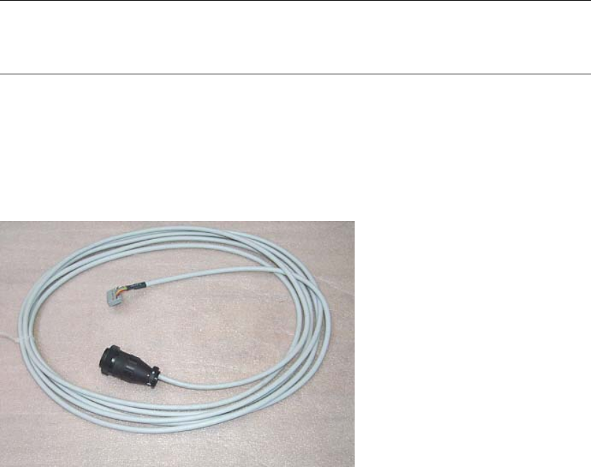
The following SMEMA interface cables are included in the delivery:
3x 00353086-02 l = 5 m, 1x socket connector 16-pin, 1x CPC
3x 00365032-02 l = 5 m, 1x socket connector 16-pin, 1x CPC
6 Making the Interface Connections Assembly Instructions
6.1 Connection to the SIPLACE Placement System SIPLACE X-Series Productivity Shuttle Type I/II
34
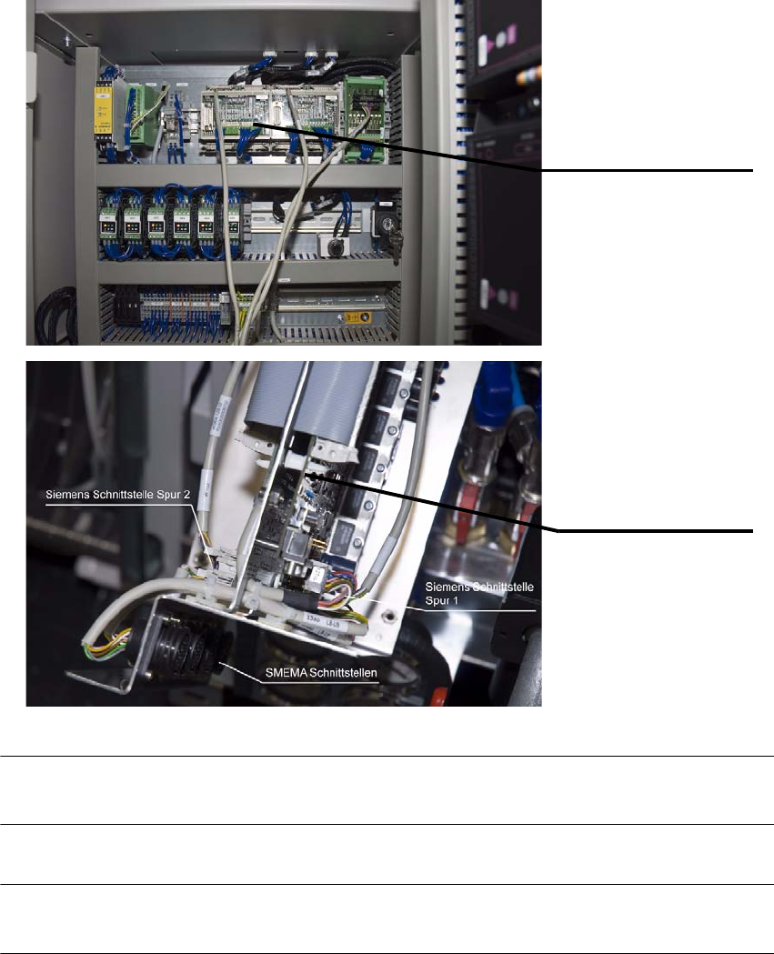
6.1 Connection to the SIPLACE Placement System
1. The SMEMA connection is made from the AMI module of the XPS to the interface connection
of the placement system.
NOTE
Refer to the circuit diagram for the XPS for the terminal markings.
NOTE
Route the cables on or under the machine to prevent them from posing a tripping hazard.
AMI 3.x - Tracks 1 and 2
Interface connections on
the placement system
35
Assembly Instructions 6 Making the Interface Connections
SIPLACE X-Series Productivity Shuttle Type I/II 6.2 Connection from XPS to XPS
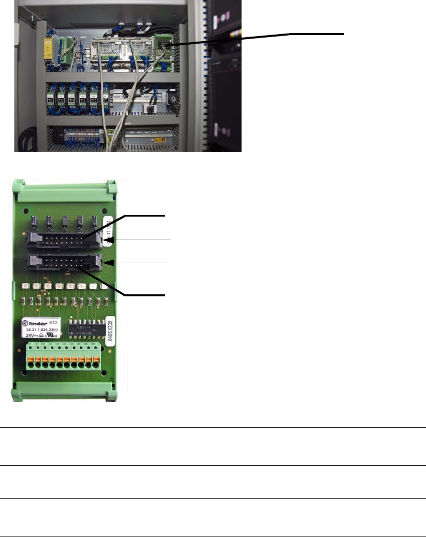
6.2 Connection from XPS to XPS
The connection from XPS to XPS (input module to intermediate module or intermediate module
to end module) is made from SIM module 1.0 to SIM module 1.0.
NOTE
Refer to the circuit diagram for the XPS for the terminal markings.
NOTE
Route the cables on or under the machine to prevent them from posing a tripping hazard.
SIM 1.0
X/N-1 to X/N+1 of the downstream XPS
X/N-1 to X/N+1 of the upstream XPS
X/N+1
X/N-1