SMEDBFeeder_UserGuide_EN.pdf - 第25页
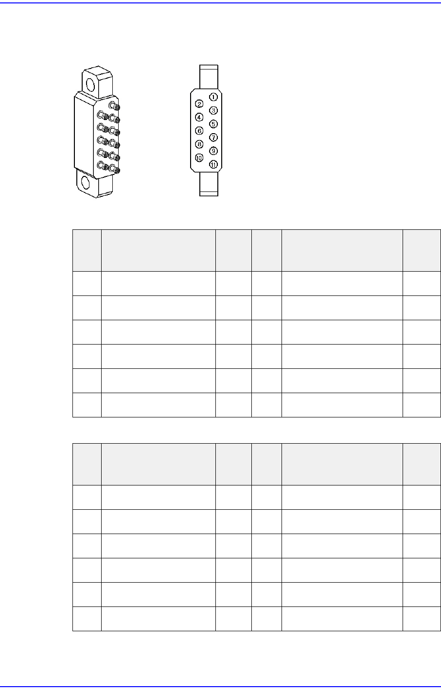
1-7 Overview 1.4. Probe Pin Components Figure1.6 Probe Pin Layout Table1.2 Prob e Pin Assignment (Non IT) Table1.3 Prob e Pin Assignment (IT) Pin No. Function Use Pin No. Function Use 1 ID0 X 7 Indexing Signal ○ 2 ID1 X …
1-6
SM-Series SME DB Tape Feeder User's Manual
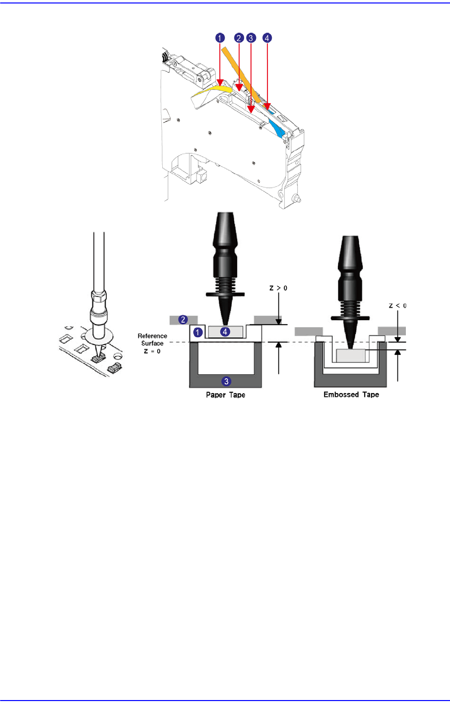
Figure1.5 SME 12~88mm tape feeder
1: Tape
2: Tape guide
3: Frame
4: Part
The Z value of the pickup point is applied in various ways according to the feeder type. In
addition, the Z value of the pickup point also varies according to the type of the part
supply tape. The embossed tape must be set according to the pocket depth and part height.
Sometimes, the pickup Z value is indicated as a negative (-) value.
1-7
Overview
1.4. Probe Pin Components
Figure1.6 Probe Pin Layout
Table1.2 Probe Pin Assignment (Non IT)
Table1.3 Probe Pin Assignment (IT)
Pin
No.
Function Use
Pin
No.
Function Use
1 ID0 X 7 Indexing Signal
○
2 ID1 X 8 Clamping Signal
○
3 D24V X 9 Indexing Command
○
4 Communication X 10 F24V
○
5 Communication X 11 F24G
○
6 D24G X
Pin
No.
Function Use
Pin
No.
Function Use
1ID0
○
7 Indexing Signal
○
2ID1
○
8 Clamping Signal
○
3 D24V
○
9 Indexing Command
○
4 Communication
○
10 F24V
○
5 Communication
○
11 F24G
○
6 D24G
○