SMEDBFeeder_UserGuide_EN.pdf - 第38页
2-12 SM-Series SME DB Tape Feeder User's Manual Caution If the length from the pickup point of the carrier tape to the front end of the tape is short, t he tape may be stuck. Therefore, make the carrier tape l ong e…
2-11
Operation of the Feeder
2.2.3. Installing the component tape and Exit of the carrier tape
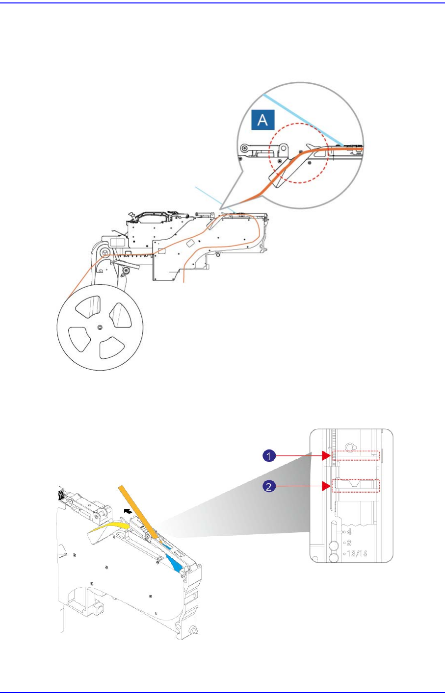
Have the tape pass through ‘A’ as shown in the following figure.
Figure2.13 Installing path of the tape
Discharge the vinyl tape by selecting one of the front or rear slits of the tape guide.
Figure2.14 Installing the upper cover tape of the feeder( Install the tape through the front/rear slit )
2-12
SM-Series SME DB Tape Feeder User's Manual
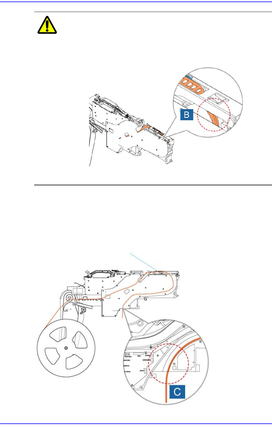
Caution If the length from the pickup point of the carrier tape to the
front end of the tape is short, the tape may be stuck.
Therefore, make the carrier tape long enough so that the
tape can pass 'B' in the following figure.
After passing the tape through the tape guide and main frame, peel the vinyl tape
approximately 30cm from the tape end and pull it out to the upper surface of the tape
guide.
Pass the carrier tape through groove C.
Figure2.15 Exit of the carrier tape of the 12~88mm
tape feeder
2-13
Operation of the Feeder
2.2.4. Locking
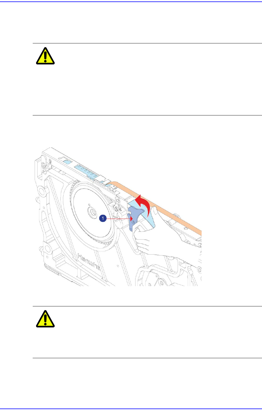
Move the tape guide down after having sprockets mesh with the transfer slots of the carrier
tape and check that the carrier tape has been properly meshed with the sprockets.
Caution Before lowering the tape guide, check whether a chip or
foreign material exists between the tape guide and main
body.
After checking whether sprockets mesh with the transfer
slots of the carrier tape, check whether the carrier tape is
transferred properly.
Ensure that the tape guide and the locker are properly locked.
Figure2.16 Checking the locking state of the tape guide and the locker
1: Locker
Caution If the tape guide and locker are not firmly secured, tape may
not be supplied or may collide with the main frame.
Therefore, be sure to check that the tape guide is secured
properly.