00196449-04_UM_FCCS_digital_DE_EN.pdf - 第59页
3 Camera Calibration in SW 605.xx Stations 3.2 Calibration Sequence in SW 605.xx Operating Manual / Bedienungsanleitung Camera Calibration FCCS digital Kamerakalibrierung FCCS digital 04/2020 59 3.2 Calibration Sequence …
3 Camera Calibration in SW 605.xx Stations
3.1 Preparations
58 Operating Manual / Bedienungsanleitung Camera Calibration FCCS digital Kamerakalibrierung FCCS digital 04/2020
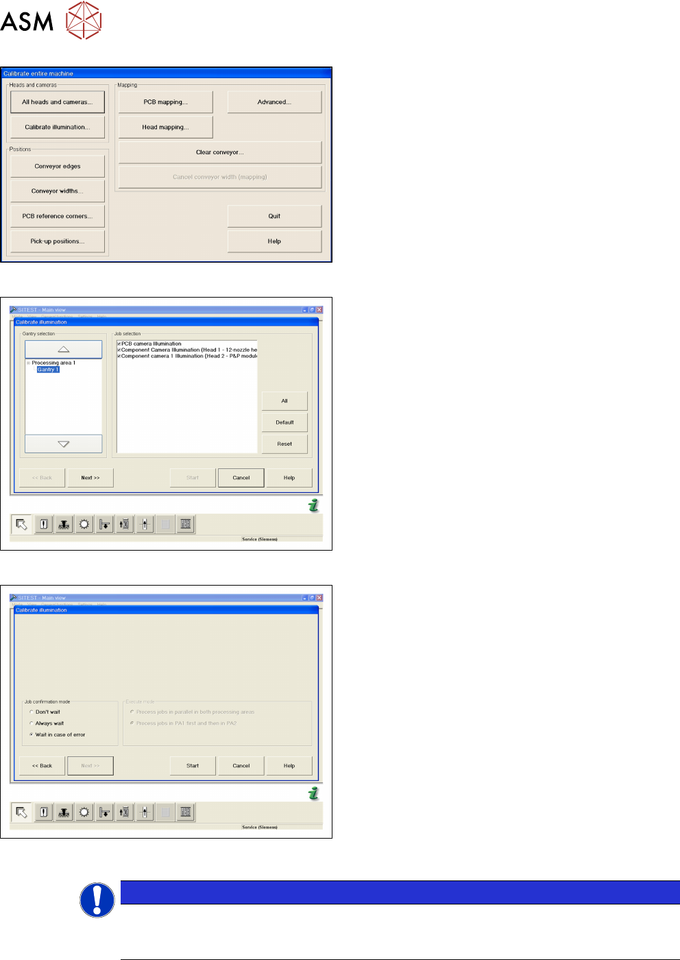
Fig.13: CALIBRATE ILLUMINATION
► Open CALIBRATE ILLUMINATION in the Cali-
brate entire machine menu.
Fig.14: Select cameras and placement areas
► Select the cameras to be calibrated and the rel-
evant placement areas.
► Confirm the selection with NEXT.
Fig.15: Select START
► Select the execution properties during the cali-
bration.
► Confirm the selection with START.
► For the further steps, follow the instructions as
you are guided through the menu.
●
Setting the width adjustment
●
Checking the nozzle configuration
●
Inserting the carrier with the white standard
NOTICE
Nozzle configuration
You can leave the SW wizard at any time in order to pick up the required nozzle types via
the single menus.
3 Camera Calibration in SW 605.xx Stations
3.2 Calibration Sequence in SW 605.xx
Operating Manual / Bedienungsanleitung Camera Calibration FCCS digital Kamerakalibrierung FCCS digital 04/2020 59
3.2 Calibration Sequence in SW 605.xx
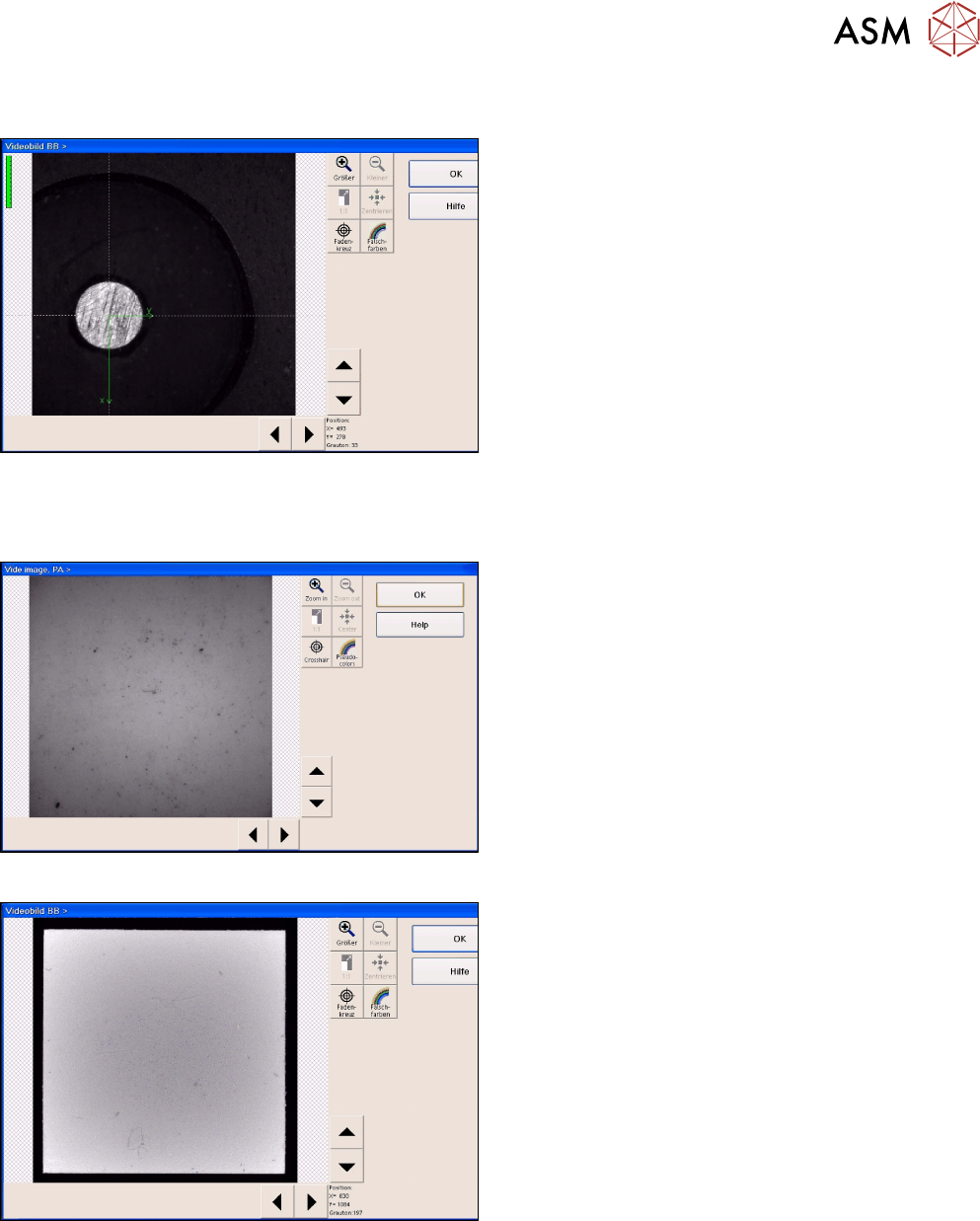
Fig.16: Position recognition of calibration tool carrier
► The PCB camera centers the 3 fiducials for posi-
tion recognition of the calibration tool carrier.
► The PCB camera is positioned to check the presence of the calibration components. Fiducial
recognition determines whether all the calibration tools are present.
Fig.17: Illumination calibration for PCB camera
► Illumination calibration is now performed for the
PCB camera. (see diagram of standard PCB
camera)
► Tray position recognition is performed again.
► The gantry placement head picks up its appro-
priate calibration tool for the component camera.
Fig.18: Video image of the component camera (C&P6 as an
example)
► The calibration tool is placed under or above the
respective component camera, the balance pro-
cess is performed and the calibration tool is re-
turned to where it was picked up from.
► The calibration procedure is repeated for the
cameras of the 2nd gantry in the placement area
or for the 2nd placement head of the gantry con-
cerned.
3.3 Final Work
► Confirm the finalization of the calibration process. The carrier with the white standards will be
transported to the output conveyor.
► Remove the tray and close SITEST.
3 Camera Calibration in SW 605.xx Stations
3.4 XML Report (SW 605.xx)
60 Operating Manual / Bedienungsanleitung Camera Calibration FCCS digital Kamerakalibrierung FCCS digital 04/2020
► When exiting SITEST, a message will be issued, informing you that machine data needs to be
saved. If you confirm this message, the values determined will be written to the camera
EPROM.
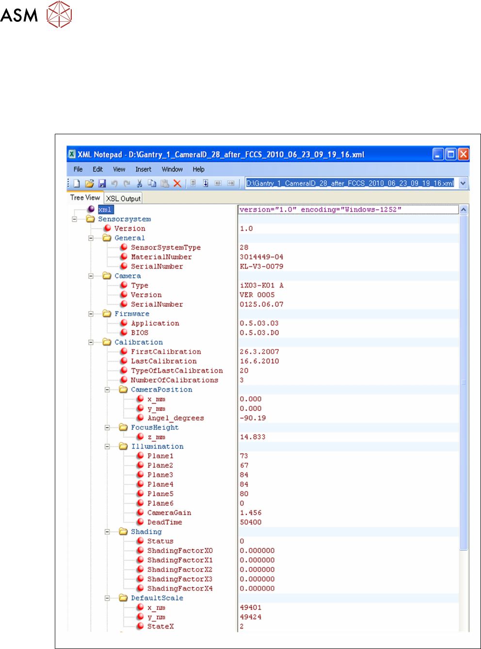
3.4 XML Report (SW 605.xx)
Excerpt from the FCCS…xml file:
Fig.19: Excerpt from the FCCS…xml file