00196449-04_UM_FCCS_digital_DE_EN.pdf - 第65页
4 Camera Calibration in Stations from SW705.03 4.1 Camera calibration from station software 709.0 und 712.1 Operating Manual / Bedienungsanleitung Camera Calibration FCCS digital Kamerakalibrierung FCCS digital 04/2020 6…

3 Camera Calibration in SW 605.xx Stations
3.4 XML Report (SW 605.xx)
64 Operating Manual / Bedienungsanleitung Camera Calibration FCCS digital Kamerakalibrierung FCCS digital 04/2020

4 Camera Calibration in Stations from SW705.03
4.1 Camera calibration from station software 709.0 und 712.1
Operating Manual / Bedienungsanleitung Camera Calibration FCCS digital Kamerakalibrierung FCCS digital 04/2020 65
4 Camera Calibration in Stations from
SW705.03
NOTICE
For report purposes you can find two XML files for each camera in C:\SR-Daten
\FCCS.
The file names have a time stamp and the following identifiers:
- gantry name
- camera type name
- before / after calibration
- date stamp
Example: Gantry_1_CameraID_25_after_FCCS_2008_06_06_14_01_28.xml
NOTICE
From SW709.0
On the station computer: C:\Sirio\Work\MaintenanceReports
On the SIPLACE Pro computer: C:\MaintenanceReports
4.1 Camera calibration from station software 709.0 und 712.1
The maintenance GUI was introduced with station software 709.0 and the function "Calibrating illu-
mination" (now "Camera verification") was moved there.
In addition, the camera check has been extended to include the function "Check camera for soiling"
from station software 712.1. This function extension can be performed separately or as a precursor
to the camera check. See also 4.5 "Calibration sequence in SW 7xx.xx" [}69]
4.2 Preparations
NOTICE
Dry run
To ensure the successful camera calibration for the complete line, it is recommended to
perform a dry run of the camera calibration without saving the calibration values.
This is necessary, because aborting the calibration will lead to different illumination values
of the cameras in the line. The reliable detection of components throughout the whole line
cannot be ensured until the camera in question has been replaced and all cameras in the
line have been re-calibrated.
To ensure that customer setups do not need to be changed, a black calibration tool carrier is
moved into PCB conveyor 1, is optically centered and clamped into place, the presence of the
white balance calibration tools is checked and illumination calibration (white balance process) is
started.
NOTICE
Pre-requisites: nozzle configuration, conveyor width etc.
You can leave the SW wizard at any time in order to pick up the required nozzle types via
the single menus.
4 Camera Calibration in Stations from SW705.03
4.3 FCCS in Placement Line as of SW 707.xx
66 Operating Manual / Bedienungsanleitung Camera Calibration FCCS digital Kamerakalibrierung FCCS digital 04/2020
From SW 705
Fig.21: Calibrate illumination
► Switch on the machine.
► Press the Start button to start the overall
reference run.
► Log in as Service (customer).
► Switch over to the SERVICE menu.
► Select Calibrate illumination.
See also …
4.7 "Report File from SW 705.03 onwards" [}72]
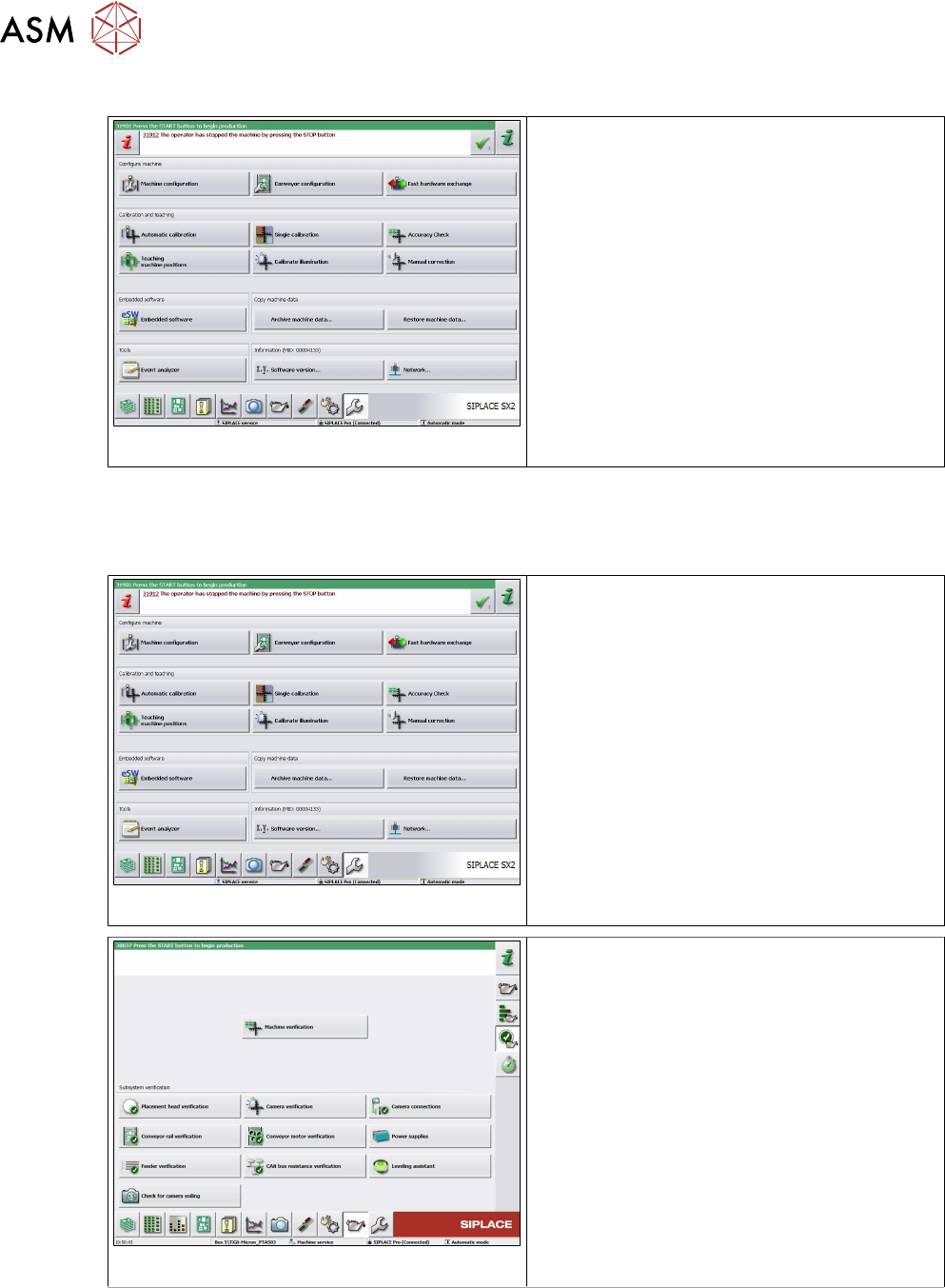
From SW 709
Fig.22: GStart overall reference run
► Switch on the machine.
► Press the Start button to start the overall
reference run.
► Log in as Service (customer).
Fig.23: Camera verification
► Switch over to the Maintenance menu.
► Select Camera verification.
4.3 FCCS in Placement Line as of SW 707.xx
Due to the fact that the conveyor area in machine types as of SIPLACE SX1/2 is difficult to access,
the following function has been integrated in the station software as of the 707.0 version.