00197190-03_VD_SIPLACE_Pro_10_1_SP1_DE_EN.pdf - 第23页
SIPLAC E Pro V10. 1 SP1 / Softwar e Version Desc ripti on Ausgabe 02/2013 Edit ion 23 Figure 4-7 : Set tings Editor Expert Mode 5.7.6 Lower Pi ck - up Tolerance Limit for Components A low er pi ck - up tolerance l im it …
SIPLACE Pro V10.1 SP1 / Software Version Description Ausgabe 02/2013 Edition
22
5.7.5 Setting Acceleration Reduction
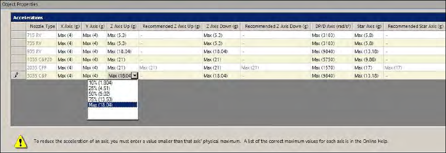
The following preset acceleration values can be selected in the Accelerations tab of the
Component Editor:
● Max (maximum acceleration)
● 75% (lightly reduced acceleration)
● 50% (medium reduced acceleration)
● 25% (highly reduced acceleration)
● 10% (extremely reduced acceleration)
The percentage values refer to the maximum acceleration of the possible placement heads. The
absolute values are displayed in brackets.
Figure 4-6: Selecting acceleration value
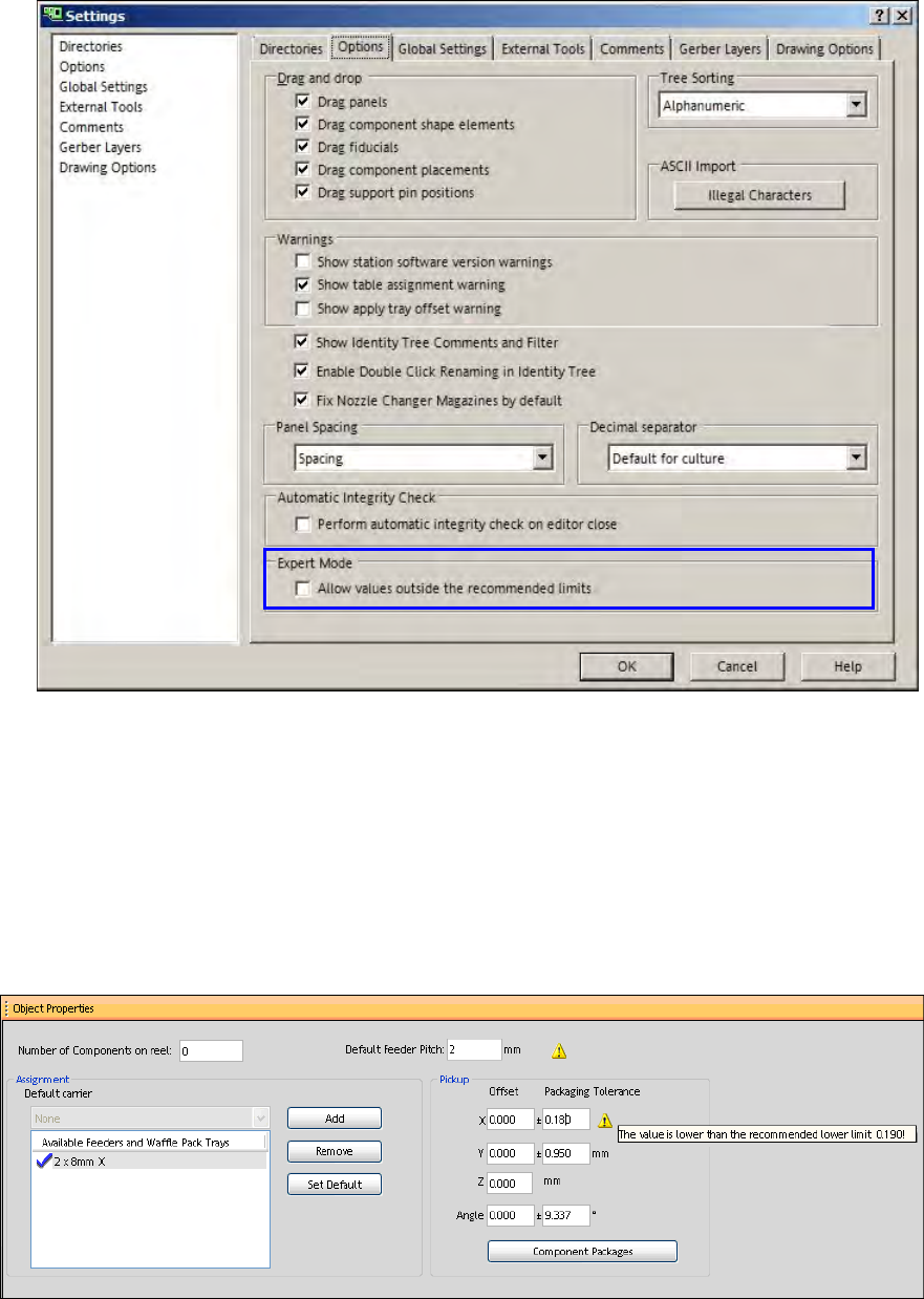
The Expert Mode allows entering values outside the recommended limits.
The values can be changed in the Data Maintenance Tool with the Suggest accelerations for
assigned Nozzles function.
Prerequisite
– The Allow entering values outside the recommended limits setting has to be enabled under
Settings – Options.
SIPLACE Pro V10.1 SP1 / Software Version Description Ausgabe 02/2013 Edition
23
Figure 4-7: Settings Editor Expert Mode
5.7.6 Lower Pick-up Tolerance Limit for Components
A lower pick-up tolerance limit has been introduced for the components. The lower limit is valid for
the X-/Y-positions and the pick-up angle at each feeder and amounts to 30% of the respective
default values that are preset when a new feeder is added under the Feeder tab in SIPLACE Pro
Desk.
If the user tries to enter a lower value, a warning displays the smallest recommended value and the
value will not be changed.
Figure 4-8: Pick-up tolerance to low for packaging unit
The Expert Mode allows entering values outside the recommended limits.
A feeder offset for multiple components can be entered and assigned in the Data Maintenance Tool
(please refer to the Set Feeder offset data of assigned Feeders – Set Feeder Offset Data
function).The same prerequisite as described in section 4.8.5 applies.
SIPLACE Pro V10.1 SP1 / Software Version Description Ausgabe 02/2013 Edition
24
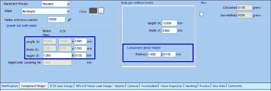
5.7.7 Lower Limit for Component Shape Dimensions
A lower tolerance limit has been introduced for the component shape dimensions. The lower limit is
valid for the length, width and height of the outer dimensions and amounts to 1% of the respective
basic sizes.
If the user tries to enter a lower value, a warning displays the smallest recommended value and the
value will not be changed.
Figure 4-9: Component shape dimensions
The Expert Mode allows entering values outside the recommended limits.
The values can be changed in the Data Maintenance Tool with the Set Feeder offset data of
assigned Feeders – Set Feeder Offset function. The prerequisite described in section 4.8.5
applies.