00197190-03_VD_SIPLACE_Pro_10_1_SP1_DE_EN.pdf - 第27页
SIPLAC E Pro V10. 1 SP1 / Softwar e Version Desc ripti on Ausgabe 02/2013 Edit ion 27 5.8.3 A utomatic Calcu latio n of th e Pick - up Position for A symmetrica l Components The calc ulated pick - up position for as ymme…
SIPLACE Pro V10.1 SP1 / Software Version Description Ausgabe 02/2013 Edition
26
Distributing the Access Authorizations via SIPLACE Pro Line Control
The access authorizations for the handling options are managed by using the different activity
levels at the station. Detailed information can be found in the Version Description for the 706.1
station software, item no. [00197043-02].
Changed access authorizations have to be manually uploaded to SIPLACE Pro. SIPLACE Pro Line
Control distributes them to all placement machines in the whole line that are switched-on at that
time. If a placement machine is switched-off or not available in the network, SIPLACE Pro Line
Control displays an error message for this station. The configuration file will not be saved by
SIPLACE Pro Line Control and the distribution will not be rerun.
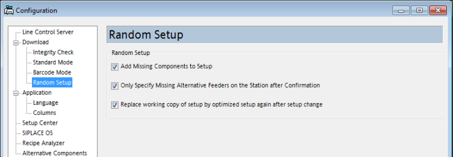
5.8.2 Random Setup Settings
As of this SIPLACE Pro version, the settings for Random Setup are placed on a separate page in
the SIPLACE Pro Line Control GUI instead of on the page with the Download settings.
Figure 4-12: Random Setup settings
SIPLACE Pro V10.1 SP1 / Software Version Description Ausgabe 02/2013 Edition
27
5.8.3 Automatic Calculation of the Pick-up Position for Asymmetrical Components
The calculated pick-up position for asymmetrical components always has to be manually corrected
in SIPLACE Pro. Until now, the calculated pick-up position was based on the component
description of symmetrical components without leads, what resulted in incorrect pick-up positions
for asymmetrical components.
As of this SIPLACE Pro version, the calculated pick-up position for asymmetrical components will
be based on the outer dimensions of the component shape.
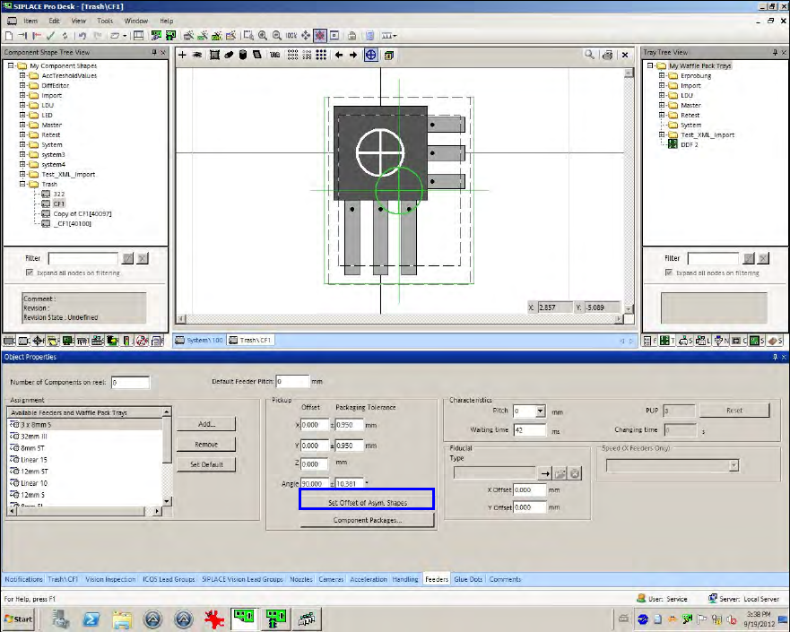
If the user selects an asymmetrical component in the Feeder tab of the Component Shape Editor,
green cross hairs will be additionally displayed at another position as the white cross hairs. The
white cross hairs display the center of the component shape without the leads/balls. The green
cross hairs display the center of the complete component shape including the leads/balls.
Figure 4-13: Automatic calculation of the pick-up positions
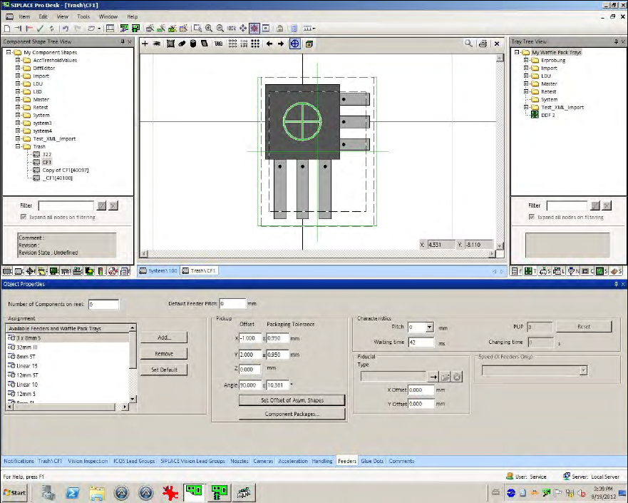
The X-/Y-positions now have to be changed so that the green cross hairs lie on the white ones.
This can be performed with the Set Offset of Asym.Shapes button.
Whenever the component shape dimensions, lead dimensions or the pick-up angle are changed,
the pick-up correction has to be performed with this button.
SIPLACE Pro V10.1 SP1 / Software Version Description Ausgabe 02/2013 Edition
28
Figure 4-14: Recalculated pick-up positions
The function can also be used in the Data Maintenance Tool (under Set Feeder offset data of
assigned Feeders).
5.8.4 Saving the X-/Y-positions
After the X-/Y-pick-up positions or the pick-up angle have been changed and the function for
uploading the feeder data is enabled at the station, the changes can be locally saved at the station
and additionally uploaded to SIPLACE Pro into the defined setup.