JUKI KE775点胶机说明书1.pdf - 第20页
CHAPTER1GENERAL 1o1ˉ 8。 Head position Correct∶ on funcIion and residual amount detection function This function appⅡ es pressure to the inside of syringe to the extentthat the adhesiVe does not come out and estimates the…
CHAPTER1GENERAL
■
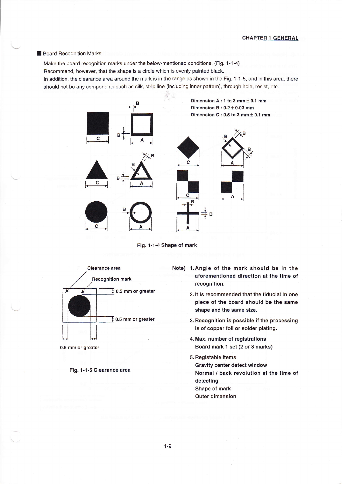
BOard Recognition Marks
Make the board recogn"ion rnarks underthe beIowˉ
mentioned cond"ions‘
(FIg,1ˉ
1ˉ 4)
Recommend,however,thatthe shape is a circIe which is evenIy painted black.
In addition,the Clearance area around the rη
ark is in the range as shown in the Fig.1ˉ
1ˉ
5,and in this area,there
should not be any components such as s"k,strip Iine(including inner pauern),through hole,resist,etC。
田mension A:1to3mm± 0.1mm
Dimension B:0.2±
0.03mm
Dirnension C:0.5to3mm± 0.丬 mm
F:g.1ˉ 1ˉ
4shape of mark
NOte) 1・ AngIe of the mark shouId be in the
aforement∶ oned direction at the time of
recogn;tion.
2."is reCoΠ 1mended thatthe fiduciaIin one
piece ofthe board should be the same
shape and the same size.
3.Recogn"ion∶
s possibIe ifthe processing
is of copperfo∶
I Or solder pIating.
4.Max。 number of registrations
Board mark1set(2°r3marks)
5.RegistabIe items
Gravity center detect window
Norma∶
'back revoIution at the time of
detecting
shape of mark
outer dimension
寺
:
o.s mm or greater
o.5mm or greater
o.5mm or greater
Fig.1ˉ
⒈5CIearance area
1-9
CHAPTER1GENERAL
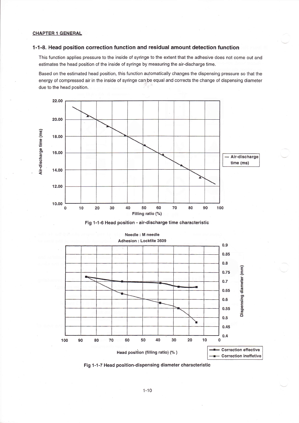
1o1ˉ8。 Head position Correct∶ on funcIion and residual amount detection function
This function appⅡ
es pressure to the inside of syringe to the extentthat the adhesiVe does not come out and
estimates the head position ofthe inside of syringe by rneasuring the airˉ
discharge tirne。
Based on the estimated head pos"ion,this function aut°
maticaⅡ y chaOges the dispensing pressure so thatthe
energy of Compressed引
rin the insde of sy"nge can巾
e equal and corrects the change of d⒗
pensing diameter
due to the head pos"ion.
-``ir・
discharge
刂
me(ms)
12.00
10.00
o 10 20 30 40 50 60 70 80 90 100
F"ing rauo(%)
Fig1ˉ 1ˉ 6Head positionˉ
a:rˉ
discharge time charaCteristiC
Needle:M needle
Adhesion:Locktite3609
`
\
●
●
冖
`
`
`
`
`
、
100 90 80 70 60 50 40 30 20 10 0
Head position(fi"ing ratio)C汔
)
-c°
rrecti。
ne矸
eC刂Ve
— c°rrecti。 n ine竹etiVe
Fig1ˉ1ˉ 7Head positionˉ
d∶
spensing diameter charaCteristIc
\
\
\
\
\
`
\
\
\
\
1ˉ 10
CHAPTER1GENERAL
1ˉ2.BasiC Configuration and Parts Ident∶
ficat∶
on
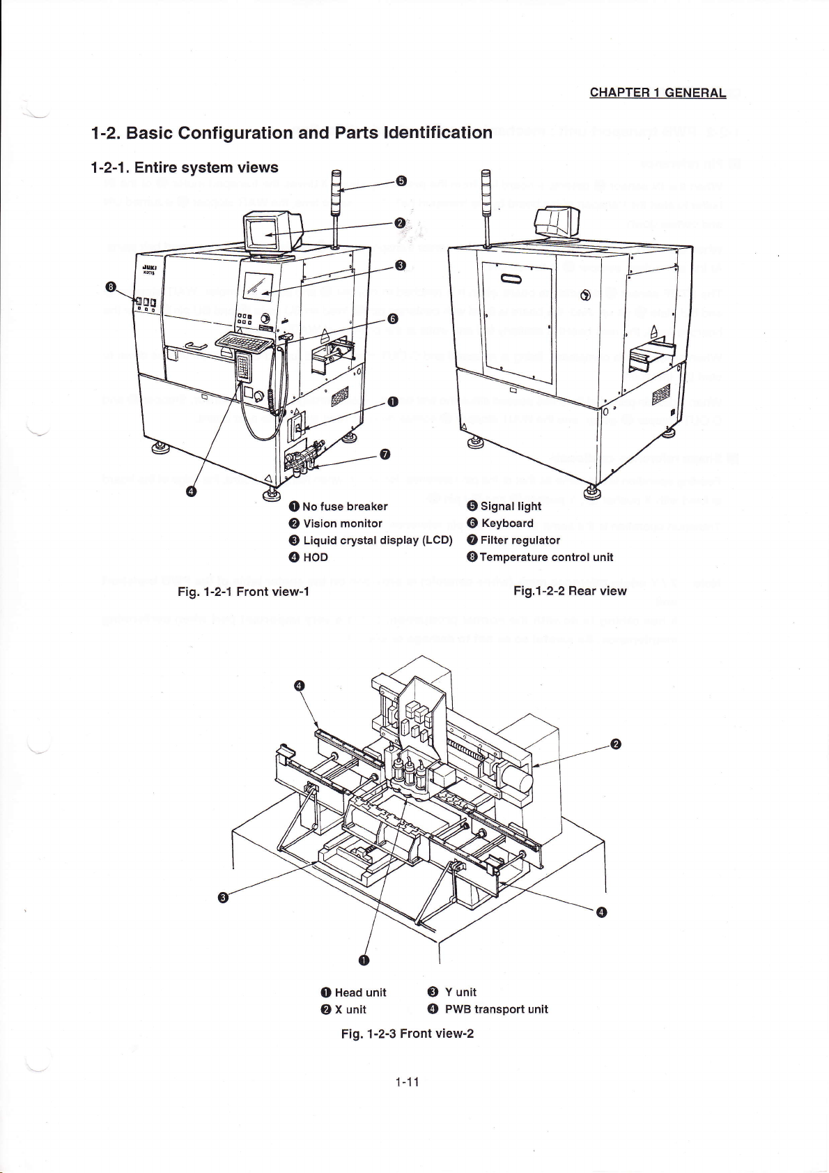
1ˉ2ˉ1。 Entire systen,vieWs
③
Liquid crystal d∶
splay(LCD)
④
H0D
Fig.1ˉ 2ˉ 1Front V∶ eWˉ
1
o signaI
Ⅱ
ght
⑥
Keyboard
⑦
F"ter reguIator
⑧
Temperature controI un"
FigJˉ
2ˉ
2Rear view
o No fuse breaker
②
Vision m°
nitor
o Head unit
③ Y unit
②
X un"
④ PWB transport unit
Fig.1ˉ
2ˉ 3Front Viewˉ
2
1ˉ 11