JUKI KE775点胶机说明书1.pdf - 第23页
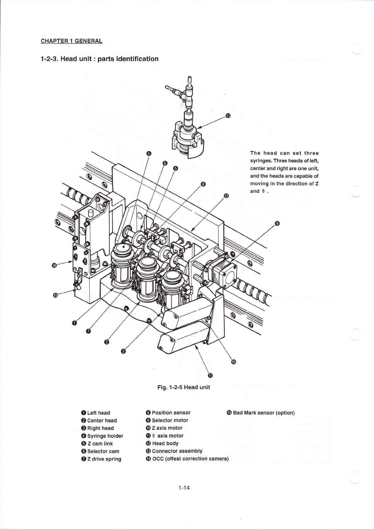
CHAPTER1GENERAL 1ˉ 2ˉ 3.Head un⒒ :pa"s identⅢ cation o Le什 head ② Center head ③ Right head 四 )syringe hoIder ⑤ z cam link ⑥ seIector cam oz drive spring Fig.1ˉ 2ˉ 5Head un∶ t C|Position sensor ⑨ selector motor ⑩ z a…
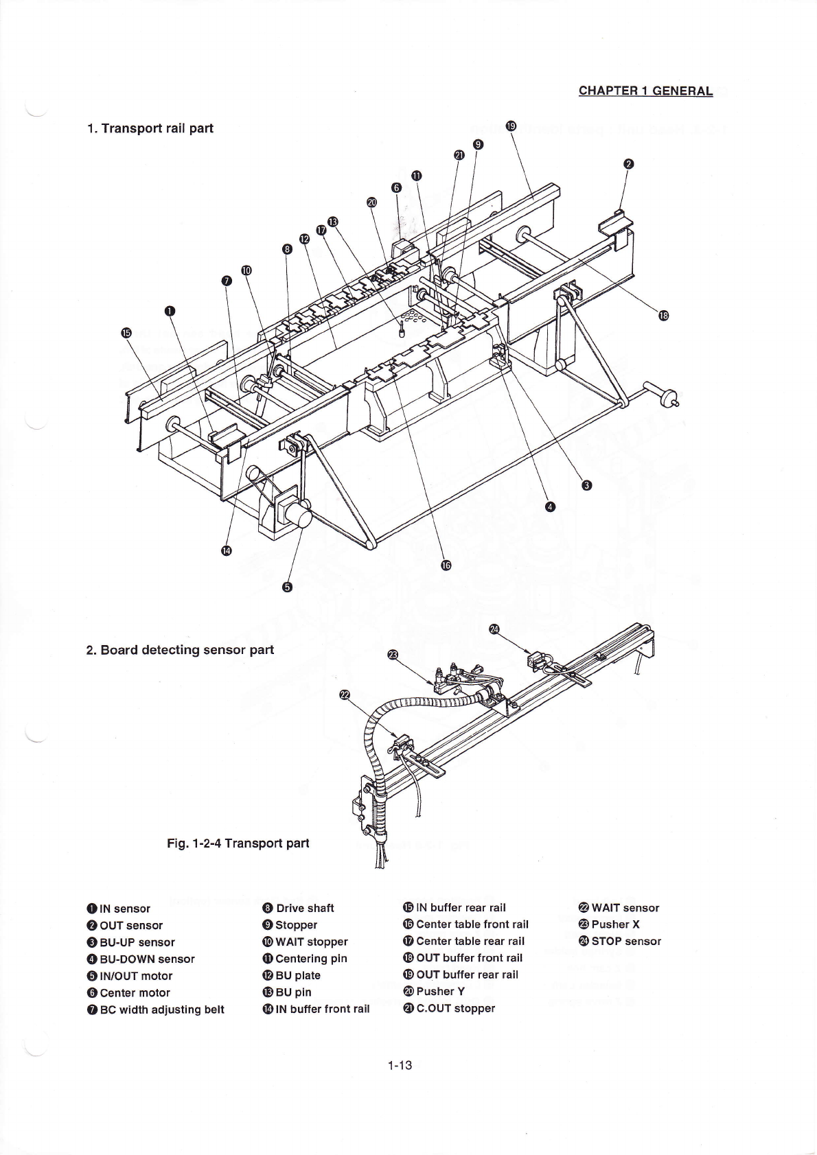
2.Board deteCt:ng sensor pa"
Fig.1ˉ
2ˉ
4Transpod part
CHApTER1GENERAL
②
WAlT sens° r
O Pusher X
四
冫
sT0P sensor
●
刂N sens°
r
②
ouT sens°
r
O BUˉ
UP sensor
④
BUˉ
D0WN sensor
⑤
IN`0uT m°
t° r
⑥
Center m°
tor
o BC width adjusting be"
】
a)D"ve shaft
‘
冫
stopper
⑩
WAIT stopper
o Centering pI卩
@BU pIate
O BU pIn
四9IN buⅡ
erfront ra"
⑩
IN buffer rear ra"
⑩
Center tabIe front ra"
o Centertable rear raⅡ
m冫
ouT bufferfront ra"
⑩
0UT bu矸er rear ra"
囫
冫
Pusher V
oC.0UT stopper
1丬
3
CHAPTER1GENERAL
1ˉ
2ˉ3.Head un⒒
:pa"s identⅢ
cation
o Le什
head
②
Center head
③
Right head
四
)syringe hoIder
⑤
z cam link
⑥
seIector cam
oz drive spring
Fig.1ˉ 2ˉ5Head un∶
t
C|Position sensor
⑨
selector motor
⑩
z axis motor
Θ
θ ax‘
motor
@Head body
⑩
Connect°
r assembIy
四
冫
oCC(offest c°
rrec刂 on camera)
The head can set three
syringes.Three heads ofIe钍
,
center and right are one un∶
t,
and the heads are capable of
moˇing in the direction of z
and θ.
o Bad Mark sensor(°
ption)
1丬 4
CHAPtER1GENERAL
1ˉ
3.EXpIanaJon of X,Y and
θ Axes
The foⅡ
oⅥ
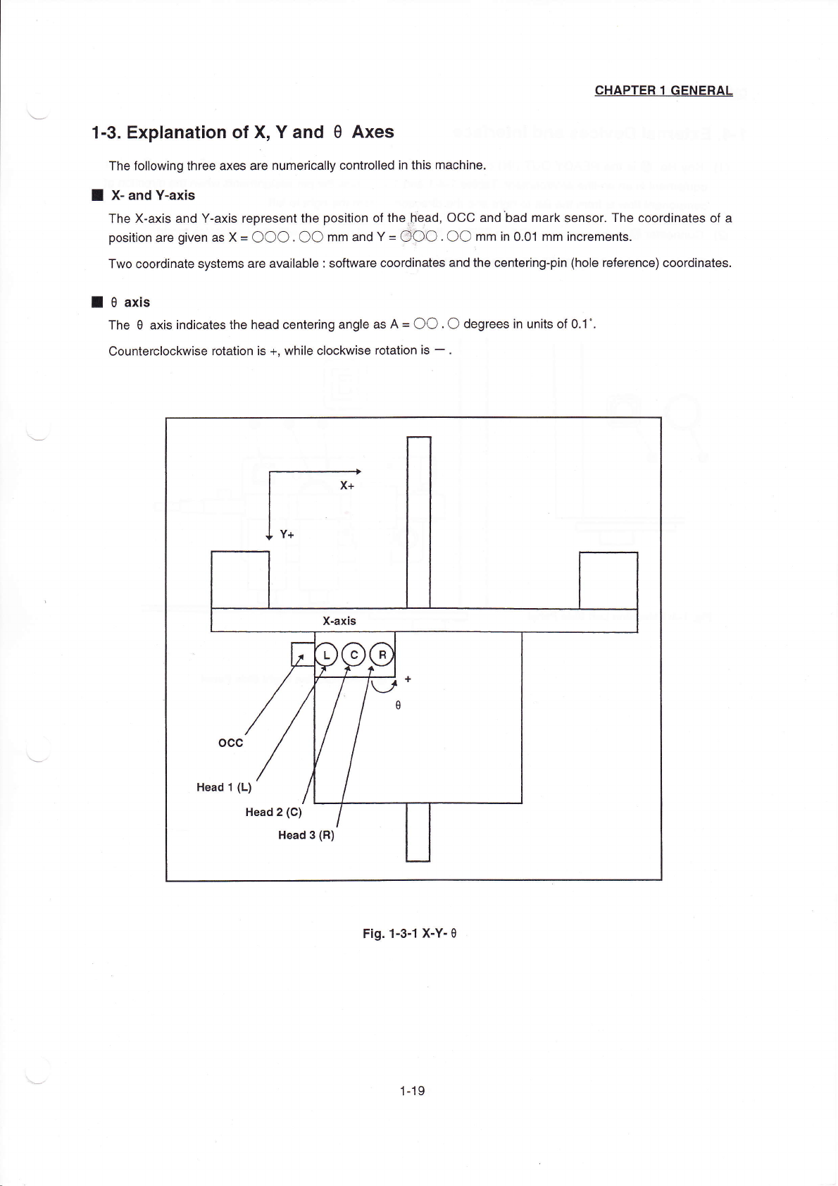
`ing three aXes are numerica"y contro"ed in this rnaChine.
■
Xˉ and Yˉ
axls
The Xˉ axis and Yˉ
aXis represent the posⅡ
ion of theⅡ
ead,0CC and bad mark sensor.The coor-inates of a
pos"on are gven as X〓
○○○○○
mm and Y〓
OOO.○○
mm in O.01mm hcrements.
TWo Coordinate systems are ava"abIe∶
software coordinates and the Cente"ng¨
pin(hole reference)coordinates,
■
θ axis
The θ axis indiCates the head centering angIe as A〓
○○
.○ degrees in un"s of O.1°
,
CountercloCkWise rotation is+,Wh"e cIockwise rotation Is-.
Head丬
(L)
Head2(C)
Head3(R)
Fig.1ˉ
3△
XˉYˉ
θ
1丬 9