JUKI KE775点胶机说明书1.pdf - 第24页
CHAPtER1GENERAL 1ˉ 3.EXpIanaJon of X,Y and θ Axes The foⅡ oⅥ `ing three aXes are numerica"y contro"ed in this rnaChine. ■ Xˉ and Yˉ axls The Xˉ axis and Yˉ aXis represent the posⅡ ion of theⅡ ead,0CC and bad ma…
CHAPTER1GENERAL
1ˉ
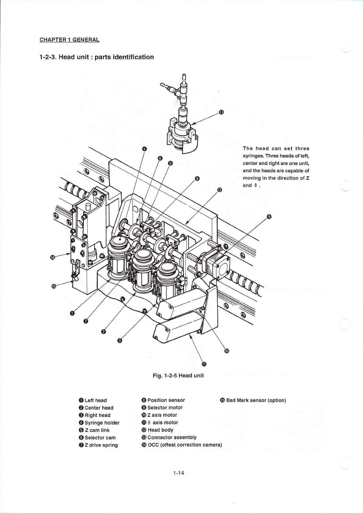
2ˉ3.Head un⒒
:pa"s identⅢ
cation
o Le什
head
②
Center head
③
Right head
四
)syringe hoIder
⑤
z cam link
⑥
seIector cam
oz drive spring
Fig.1ˉ 2ˉ5Head un∶
t
C|Position sensor
⑨
selector motor
⑩
z axis motor
Θ
θ ax‘
motor
@Head body
⑩
Connect°
r assembIy
四
冫
oCC(offest c°
rrec刂 on camera)
The head can set three
syringes.Three heads ofIe钍
,
center and right are one un∶
t,
and the heads are capable of
moˇing in the direction of z
and θ.
o Bad Mark sensor(°
ption)
1丬 4
CHAPtER1GENERAL
1ˉ
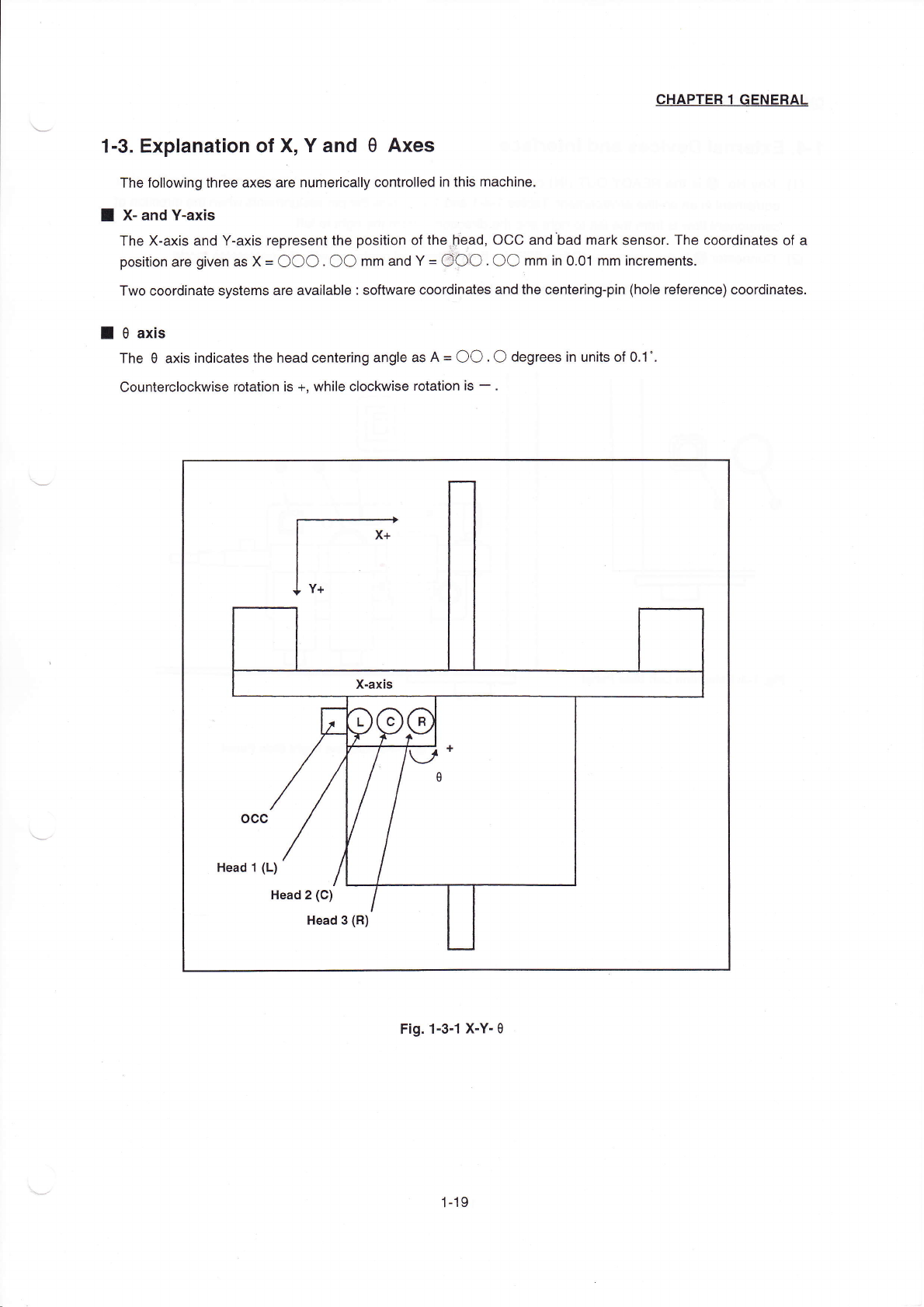
3.EXpIanaJon of X,Y and
θ Axes
The foⅡ
oⅥ
`ing three aXes are numerica"y contro"ed in this rnaChine.
■
Xˉ and Yˉ
axls
The Xˉ axis and Yˉ
aXis represent the posⅡ
ion of theⅡ
ead,0CC and bad mark sensor.The coor-inates of a
pos"on are gven as X〓
○○○○○
mm and Y〓
OOO.○○
mm in O.01mm hcrements.
TWo Coordinate systems are ava"abIe∶
software coordinates and the Cente"ng¨
pin(hole reference)coordinates,
■
θ axis
The θ axis indiCates the head centering angIe as A〓
○○
.○ degrees in un"s of O.1°
,
CountercloCkWise rotation is+,Wh"e cIockwise rotation Is-.
Head丬
(L)
Head2(C)
Head3(R)
Fig.1ˉ
3△
XˉYˉ
θ
1丬 9
CHAPTER1GENERAL
1冖4.
(1)
ExternaI Devices and Interface
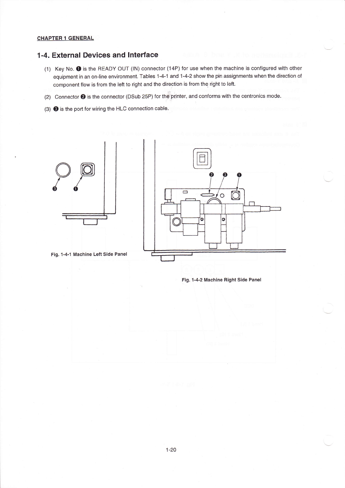
Key No.●
isthe READY OUT(丨
N)Connector(14P)for use when the machine is configured w"h other
equipmentin an on丬
ine environment.TabIes1ˉ
4ˉ
1and1ˉ 4ˉ 2shoW the pin assignments when the direction of
component"ovv is from the IeR to right and the dirρ
ρ
tion is from thq righttO Ien,
COnnector叼
"s the connector(DSub25P)for th甘
0"nter,and conforms W"h the centronics mode.
0is the port for vvi"ng the HLC connection cable.
Fig.1ˉ4ˉ
1 MaChine Len side Panel
Fig.1ˉ
4ˉ2MaChine Right side Panel
1-20