JUKI KE775点胶机说明书1.pdf - 第21页
CHAPTER1GENERAL 1ˉ 2.BasiC Configuration and Parts Ident∶ ficat∶ on 1ˉ 2ˉ 1。 Entire systen,vieWs ③ Liquid crystal d∶ splay(LCD) ④ H0D Fig.1ˉ 2ˉ 1Front V∶ eWˉ 1 o signaI Ⅱ ght ⑥ Keyboard ⑦ F"ter reguIator ⑧ Temperatu…
CHAPTER1GENERAL
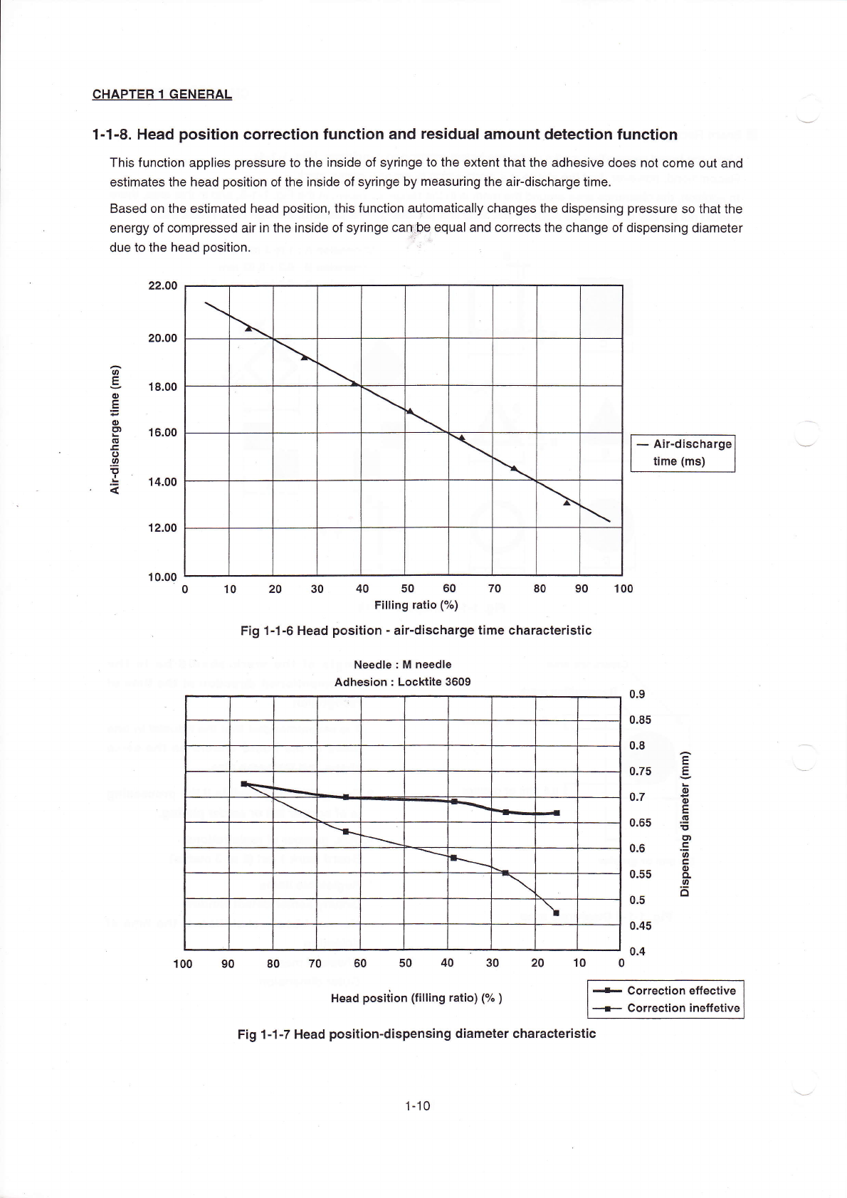
1o1ˉ8。 Head position Correct∶ on funcIion and residual amount detection function
This function appⅡ
es pressure to the inside of syringe to the extentthat the adhesiVe does not come out and
estimates the head position ofthe inside of syringe by rneasuring the airˉ
discharge tirne。
Based on the estimated head pos"ion,this function aut°
maticaⅡ y chaOges the dispensing pressure so thatthe
energy of Compressed引
rin the insde of sy"nge can巾
e equal and corrects the change of d⒗
pensing diameter
due to the head pos"ion.
-``ir・
discharge
刂
me(ms)
12.00
10.00
o 10 20 30 40 50 60 70 80 90 100
F"ing rauo(%)
Fig1ˉ 1ˉ 6Head positionˉ
a:rˉ
discharge time charaCteristiC
Needle:M needle
Adhesion:Locktite3609
`
\
●
●
冖
`
`
`
`
`
、
100 90 80 70 60 50 40 30 20 10 0
Head position(fi"ing ratio)C汔
)
-c°
rrecti。
ne矸
eC刂Ve
— c°rrecti。 n ine竹etiVe
Fig1ˉ1ˉ 7Head positionˉ
d∶
spensing diameter charaCteristIc
\
\
\
\
\
`
\
\
\
\
1ˉ 10
CHAPTER1GENERAL
1ˉ2.BasiC Configuration and Parts Ident∶
ficat∶
on
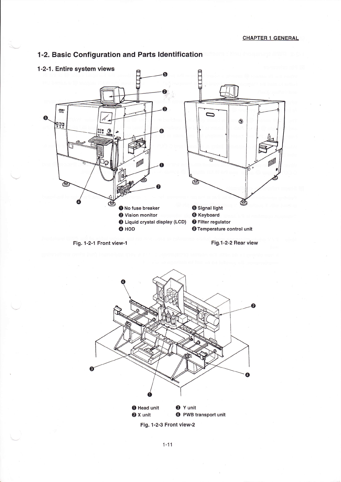
1ˉ2ˉ1。 Entire systen,vieWs
③
Liquid crystal d∶
splay(LCD)
④
H0D
Fig.1ˉ 2ˉ 1Front V∶ eWˉ
1
o signaI
Ⅱ
ght
⑥
Keyboard
⑦
F"ter reguIator
⑧
Temperature controI un"
FigJˉ
2ˉ
2Rear view
o No fuse breaker
②
Vision m°
nitor
o Head unit
③ Y unit
②
X un"
④ PWB transport unit
Fig.1ˉ
2ˉ 3Front Viewˉ
2
1ˉ 11
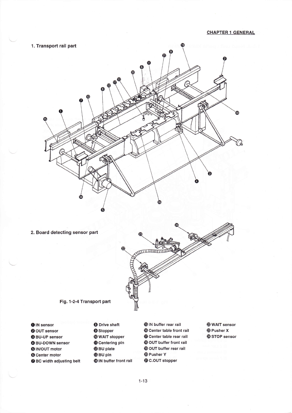
2.Board deteCt:ng sensor pa"
Fig.1ˉ
2ˉ
4Transpod part
CHApTER1GENERAL
②
WAlT sens° r
O Pusher X
四
冫
sT0P sensor
●
刂N sens°
r
②
ouT sens°
r
O BUˉ
UP sensor
④
BUˉ
D0WN sensor
⑤
IN`0uT m°
t° r
⑥
Center m°
tor
o BC width adjusting be"
】
a)D"ve shaft
‘
冫
stopper
⑩
WAIT stopper
o Centering pI卩
@BU pIate
O BU pIn
四9IN buⅡ
erfront ra"
⑩
IN buffer rear ra"
⑩
Center tabIe front ra"
o Centertable rear raⅡ
m冫
ouT bufferfront ra"
⑩
0UT bu矸er rear ra"
囫
冫
Pusher V
oC.0UT stopper
1丬
3