00197442-03_VD_707_1_SP2_DE_EN.pdf - 第16页
Station S oftware 70 7.1 SP2 / Ver sion Desc ription Ausgabe 11/2014 E dition 16 6.7 SIPL A CE V ision Enhancem ents The SI PLACE Vision s ys tem has been en hanced as f ollows. 6.7.1 Reading PCB Barco de s with the PCB …
Station Software 707.1 SP2 / Version Description Ausgabe 11/2014 Edition
15
6.5 Placement Process for Springs
Compatible mode: Not supported
The station software provides a new travel profile to support the placement process for springs.
Special parameters have to be set in SIPLACE Pro for this placement process.
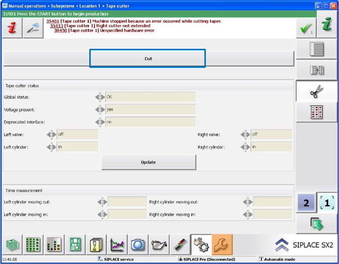
6.6 Displaying Cutting Times per Compressed Air Cylinder on the
GUI
Compatible mode: Complete
The cutting times per compressed air cylinder can be displayed on the station software GUI. Thus,
the sensor positions can be checked quickly and the sensors adjusted if necessary.
The measurement of the cutting times is activated via the Cut button under Manual operations –
Subsystems.
Figure 5-1: Measurement of cutting times
The measured times for moving out and moving back the cylinder are displayed in a table in
milliseconds on the GUI for the left and right cylinders respectively.
The measurement only takes place within the Manual operations and not during production.
Station Software 707.1 SP2 / Version Description Ausgabe 11/2014 Edition
16
6.7 SIPLACE Vision Enhancements
The SIPLACE Vision system has been enhanced as follows.
6.7.1 Reading PCB Barcodes with the PCB Camera
Compatible mode: Complete
Until now, a USB dongle containing the necessary software licenses was required for reading PCB
barcodes with the PCB camera.
As of this station software version, another method may be used alternatively with which no USB
dongle is required. The feature is realized via an internal algorithm and only the software licenses
are required.
Detailed information can be found in the respective Installation Manuals to PCB Barcode, item no.
[00197222-xx] and item no. [00197413-xx]
6.7.2 Displaying Polygon Shapes
Compatible mode: Complete
Polygons are now also displayed on the SIPLACE Vision GUI.
6.7.3 Accuracy of Polygon Circles
Compatible mode: Complete
The accuracy of polygon circle features has been improved.
6.7.4 Displaying Component Shape when Teaching Local Fiducials
Compatible mode: Complete
Soldering pad patterns are used as local fiducials for components that require an exact placement
position. In this case it might be difficult to determine the center of the local fiducial. When defining
the reference point, cross hairs and quads are displayed to help aligning the reference point
manually.
Optionally, the component shape of the component that shall be placed at this position may be
displayed. The reference point of the component shape (= placement position) determines the
reference point of the taught fiducial. I.e., it is assumed that the position of the taught local fiducial
is equal to the placement position of the component in the board description.
6.7.5 Multiple Measurements with CPP Placement Head
Multiple measurements can be performed with the CPP placement head via the stationary camera
in Pick&Place mode. Thus, the component range has been extended.
Station Software 707.1 SP2 / Version Description Ausgabe 11/2014 Edition
17
7 Hardware Specifications
7.1 Supported Feeder Types
The following feeders are supported by the 707.1 SP2 station software version:
– 4 mm – 104 mm X-feeder
– 2x8 mm X-feeder
– 16 mm XN-feeder
– 12 V2 X-feeder
– Surftape AX (8 mm, 12 mm, 16 mm)
– LED feeder TE
LED feeder HS
– Glue Feeder
– TrayStack Feeder AX (X4i S on location 2 and 3 only)
– SIPLACE JTF-S (X-series S and SX1/SX2 V2 only)
– SIPLACE JTF-M (X-series S, X4i S micron and SX1/SX2 V2 only)
– Arbitrary Carrier X (X-series only)
– Carrier X (XTH) (X2, X3, X4 on location 2 and 4 only)
– Carrier SX (SX1/SX2 with Twin Head and CPP head only)
– FFI feeders:
HanSan LED feeder
Top Engineering LED feeder
Data IO RoadRunners
– IPTE Multi Stick Feeder:
IPTE multi stick 60 AX
IPTE multi stick XL80 AX
– Stick feeder with X-adapter
– Label feeder with X-adapter
– Reject conveyor with X-adapter
– Dip module for X-tables (LDU_X)
– MTC2 (X2, X3, X4 on location 2 and 4, X2 S, X3 S, X4 S on location 2)
– WPC5/WPC6 (SX1/SX2, X-series S on location 2)
– SIPLACE Wafer Systems (CA-series only)
– Splice sensor X-feeder