00197442-03_VD_707_1_SP2_DE_EN.pdf - 第20页
Station S oftware 70 7.1 SP2 / Ver sion Desc ription Ausgabe 11/2014 E dition 20 7.3 Component R ang e Component range for CPP head W it h type 28 component camera (C&P 18 . 7 x 18 . 7 mm digita l) With type 29 compo…

Station Software 707.1 SP2 / Version Description Ausgabe 11/2014 Edition
19
Component camera
Camera
type
Twin
head
VHF P&P
head
Twin VHF
head
5)
C&P12
head
C&P
6 x 6 mm digital
23
- - - -
C&P
6 x 6 mm digital
41
- - - -
C&P
18.7 x 18.7 mm digital
28
- - -
(default)
C&P
27 x 27 mm digital
29
- - - -
C&P
27 x 27 mm digital
30
- - -
(optional)
C&P
16 x 16 mm digital
38
- - - -
Stat. P&P
16 x 16 mm digital
2
)
25
(optional)
(optional)
(optional) -
Stat. P&P
55 x 45 mm digital
2)
33
(default)
(default)
(default) -
Stat. P&P
32 x 32 mm digital
36
(optional) - - -
Table 7-2: Component cameras, part 2
5)
Only supported on SX1/SX2 V2 placement machines with one gantry at a higher position.
7.2.2 Board Cameras
Board camera
Camera
type
SIPLACE
X-series /
X-series S
SIPLACE
SX-
series
SIPLACE
DX-series
SIPLACE
CA-series
28 digital 34 (default) (default) (default) (default)
28 digital 34HU (default)
1)
Multicolor 28 digital 24 (optional)
Table 7-3: Board cameras
1)
Only supported on the SX1/SX2 V2 placement machines with one gantry at a higher position.
Station Software 707.1 SP2 / Version Description Ausgabe 11/2014 Edition
20
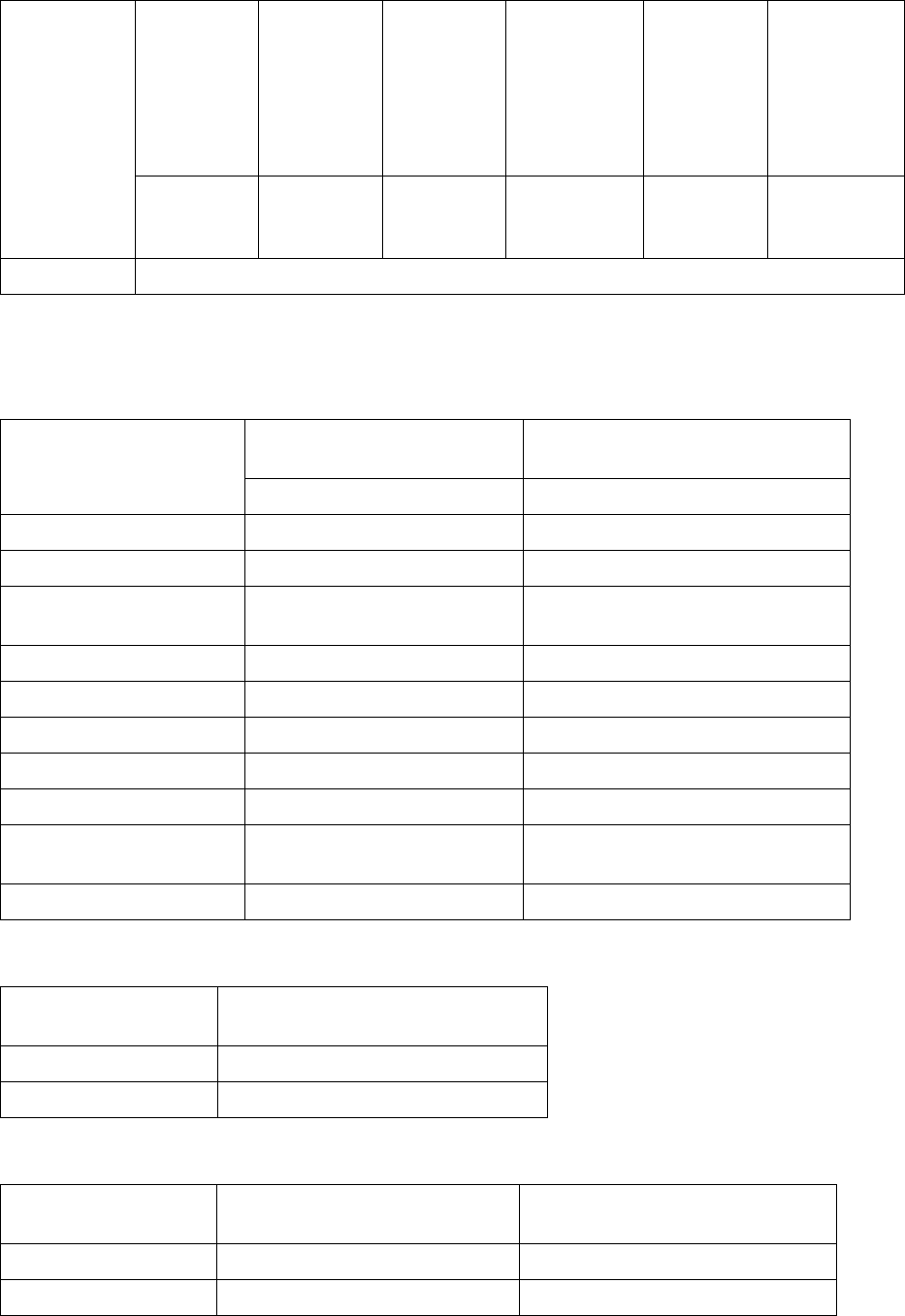
7.3 Component Range
Component
range for
CPP head
With type 28
component
camera
(C&P
18.7 x 18.7
mm digital)
With type 29
component
camera
(C&P
27 x 27 mm
digital)
With default
type 30
component
camera
(C&P
27 x 27 mm
digital)
With type 38
component
camera (C&P
16 x 16 mm
digital)
With type 33
component
camera
(Stat. P&P
55 x 45 mm
digital)
With type 36
component
camera
(Stat. P&P
32 x 32 mm
digital)
0402
through 18.7
x 18.7 mm
01005
*)
through 27 x
27 mm
01005
through 27 x
27 mm
01005 through
16 x 16 mm
(0603)
through
55 x 45 mm
0603 through
32 x 32 mm
Nozzle types 20xx, 28xx
Table 7-4: Component range CPP head
*)
If components with an edge length between 0.19 and 0.26 mm are taught, a warning is displayed,
that the placement quality may be less than specified.
Component range for
C&P20A head
With default type 23 component
camera (C&P 6 x 6 mm digital)
With high-resolution type 41
component camera (C&P 6 x 6 digital)
01005 through 2220 01005 through 2220
Component specification
min dimenstions
0.18 x 0.18 mm 0.12 x 0.12 mm
max. dimensions
6 x 6 mm (incl. component
tolerances)
6 x 6 mm (incl. component tolerances)
min. lead pitch
0.25 mm 0.08 mm
min. lead width
0.1 mm 0.03 mm
min. ball pitch
0.4 mm 0.1 mm
min. ball diameter
0.2 mm 0.,05 mm
Field of vision
8.4 x 8.4 mm 8.9 x 8.9 mm
Method of illumination
Front-illumination (5 levels,
programable as required)
Front-illumination (5 levels,
programable as required)
Nozzle types 10 xx, 11 xx, 12 xx 10 xx, 11 xx, 12 xx
Table 7-5: Component range C&P20A head
Component range for
C&P20 M head
With high-resolution type 41 component
camera (C&P 6 x 6 digital)
01005 through 2220
Nozzle types
1xxx
Table 7-6: Component range C&P20 M head
Component range for
C&P20 P head
With default type 23 component
camera (C&P 6 x 6 mm digital)
With high-resolution type 41
component camera (C&P 6 x 6 digital)
01005 through 2220
01005 through 2220
Nozzle types
4xxx
4xxx
Table 7-7: Component range C&P20 P head

Station Software 707.1 SP2 / Version Description Ausgabe 11/2014 Edition
21
Component range for
Twin Head
With type 25
component camera
(Stat. P&P 16 x 16
mm digital)
With default type 33
component camera (Stat.
P&P 55 x 45 mm digital)
With type 36 component
camera (Stat. P&P 32 x
32 mm digital)
0201 through 16 x
16 mm
0402 through 55 x 45 mm 0603 through 32 x 32 mm
Nozzle types 5 xx (standard), 4 xx + adapter, 8 xx + adapter, 9xx + adapter
Table 7-8: Component range Twin Head
Component range for
VHF P&P head
With type 25 component camera
(Stat. P&P 16 x 16 mm digital)
With default type 33 component camera
(Stat. P&P 55 x 45 mm digital)
0201 through 16 x 16 mm 0402 through 55 x 45 mm
Nozzle types 5 xx (standard), 4 xx + adapter, 8 xx + adapter, 9xx + adapter
Table 7-9: Component range VHF P&P head
Component range for
Twin VHF head
With type 25 component camera (Stat.
P&P 16 x 16 mm digital)
With default type 33 component
camera (Stat. P&P 55 x 45 mm
digital)
0201 through 16 x 16 mm 0402 through 55 x 45 mm
Nozzle types 5xx (standard), 5xxx, 4xx + adapter, 8xx + adapter, 9xx + adapter
Table 7-10: Component range Twin VHF head
Component range for
C&P12 head
With default type 28 component
camera (C&P 18,7 x 18,7 mm
digital)
With type 30 component camera
(C&P 27 x 27 mm digital)
0402 through 18.7 x 18.7 mm 0201
*)
through 27 x 27 mm
Nozzle types 30xx
Table 7-11: Component range C&P12 head
*)
0201 components can only be placed restrictively.