ITT-Cannon-RF50-Catalog.pdf - 第13页
Cannon 50 Ohm Connectors COMMERCIAL SMA Heading_1 Cannon’s Commercial SMA connectors are subminiature devices that provide repeatable electrical performance through the frequency range DC to 18.0 GHz. These 50 ohm connec…
Cannon 50 Ohm Connectors PRECISION SMA
12
www
.ittcannon.com
Dimensions shown in mm (inch)
Specifications and dimensions subject to change
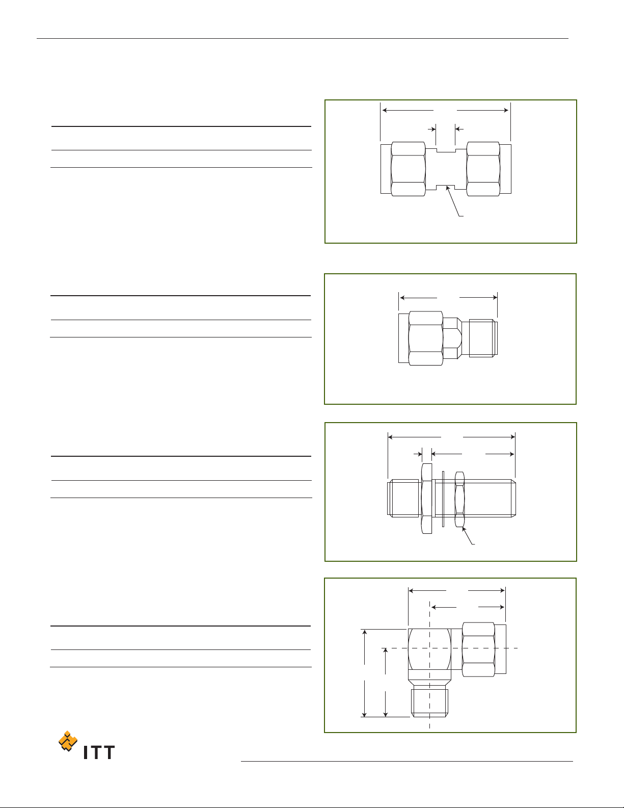
IINN--SSEERRIIEESS AADDAAPPTTOORRSS
Plug to Plug Adaptor, Straight
Part Number
050 - 673 - 0000890
22,23
(.875)
3,18
(.125)
5,56
(.219)
A
/F
2 FLATS
Plug to Jack Adaptor, Straight
Part Number
050 - 674 - 0000890
1
7,04
(.671)
Mounting Plan W (P
age 40
Jack to Jack Adaptor, Bulk Head Mount, Straight
Part Number
050 - 675 - 0000890
22,23
(.875)
1,65
(.065)
14,65
(.575)
7,92
(.312)
A/F HEX
Plug to Jack Adaptor, Right Angle
P
art Number
050 - 678 - 0000890
14,86
(.585)
11,68
(.460)
15,88
(.625)
12,70
(.500)
The surface finish on these products is passivated stainless
steel. For gold plated versions change last three digits of
the the part number from 890 to 310.
Cannon 50 Ohm Connectors COMMERCIAL SMAHeading_1
Cannon’s Commercial SMA connectors are subminiature
devices that provide repeatable electrical performance
through the frequency range DC to 18.0 GHz. These 50
ohm connectors offer minimum attenuation with low
reflection which makes them extremely popular in the
R
F and microwave industry. The MIL-C -39012 series
SMA interface ensures they can be mated with all
connectors meeting the MIL specification dimensions.
They are designed for use with a variety of subminiature
coaxial cables. This includes semi-rigid and hand
formable cables as well as the popular RG series of
flexible cable and commercial cables meeting these
dimensions.
These SMA connectors feature stand-off legs on the PCB
mount designs to enhance soldering, cleaning and
inspection. The straight plugs feature crimp / solder
contacts for speed of assembly and high performance.
SMA connectors are found in many diverse applications
including amplifiers, dividers, filters and attenuators.
The standard units are supplied in gold plate. Nickel
plated versions are available on request.
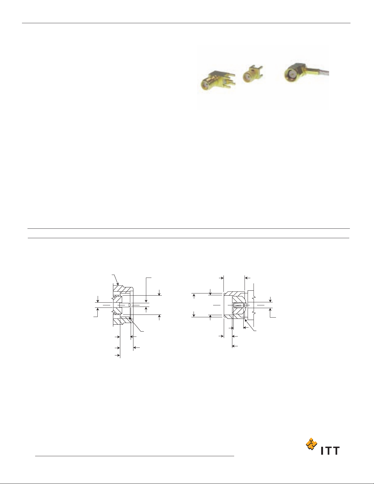
4,83
(.190)
MIN
Ø5,44
(.214)
MAX
Ø4,62
(.182)
1,98
(.078)
MAX
REFERENCE
PLANE
REFERENCE PLANE
PLUG JACK
.250-36,
UNS-2B
THD.
.250-36,
UNS-2A
THD.
2,92
(.115)
Ø1,27
(.050)
Ø0.91
(.036)
Ø4,55
(.179)
7,92
(.312)
A/F HEX
Ø1.27
(.050)
2,54
(.100)
MAX
2,54
(.100)
MAX
MMAATTIINNGG IINNTTEERRFFAACCEESS
13
www.ittcannon.com
Dimensions shown in mm (inch)
Specifications and dimensions subject to change
Key Features
• Crimp /solder contacts on straight plugs
and bulkhead jacks
• Stand-off legs on PCB mounts
• Intermateable with all SMAs to MIL-C -39012

www
.ittcannon.com
Dimensions shown in mm (inch)
Specifications and dimensions subject to change
14
Cannon 50 Ohm Connectors COMMERCIAL SMA
ELECTRICAL
Impedance
Frequency Range
Voltage Rating
50Ω
0 to 18.0 GHz
for RG-402 & RG-405 semi-rigid cable - 0 to 18 GHz
f
or flexible cable - 0 to the maximum frequency of the cable per MIL-C -17
R
G402 (0.141” OD.) 550 volts rms maximum
RG405 (0.085” OD.) 335 volts rms maximum
RG58, 141, 142, 223 550 volts rms maximum
RG174, 188, 316 335 volts rms maximum
5000 MΩ minimum
C
enter Contact = 5.0 mΩ maximum
Outer Contact = 1.0 mΩ maximum
0.04 dB maximum x f GHz (straight)
0.06 dB maximum x f GHz (right angle)
-(90-f GHz) dB minimum
1.05+0.15 x f GHz maximum (straight)
1.15+0.15 x f GHz maximum (right angle)
RG402 (0.141” OD) 1.05+0.005 x f GHz maximum
RG405 (0.085” OD) 1.05+0.005 x f GHz maximum
RG58, 141, 142, 223 1.10+0.01 x f GHz maximum (straight)
1.15+0.02 x f GHz maximum (right angle)
RG174, 188, 316 1.15+0.01 x f GHz maximum (straight)
1.18+0.02 x f GHz maximum (right angle)
RG402 (0.141” OD) 1000 volts rms maximum
RG405 (0.085”OD) 750 volts rms maximum
RG58, 141, 142, 223 1000 volts rms maximum
RG174, 188, 316 750 volts rms maximum
1/4” - 36 threaded coupling
500 matings
Minimum 60 lbs
8 inch-pounds
RG58, 141, 142, 223 40 lbs minimum
RG174, 188, 316 20 lbs minimum
-65˚C to 165˚C
MIL-STD -202 Method 204 test condition D
MIL
-STD-202, Method 101, test condition B
MIL-STD -202, Method 102 test condition C
Material Plating
Brass
Gold or nickel
Male:
Brass Gold over nickel
Female: beryllium-copper Gold over nickel
Teflon None
Silicone
None
Annealed Copper Same as body
Insulation Resistance
Contact Resistance
Insertion Loss
RF Leakage
Voltage Standing Wave Ratio (VSWR)
Dielectric Withstanding Voltage
Mating
Durability
Coupling Nut Retention
Recommended Nut Mating Torque
Cable Retention
Temperature Range
Vibration
Salt Spray
T
emperature Cycling
Connector Body
Center Contact
Insulation
Gasket
Crimp Ferrule
MECHANICAL & ENVIRONMENTAL
MA
TERIAL
SSPPEECCIIFFIICCAATTIIOONNSS