ITT-Cannon-RF50-Catalog.pdf - 第48页
Cannon 50 Ohm Connectors ASSEMBL Y INSTRUCTIONS A A I I - - 3 3 0 0 2 2 S S M M A A S S t t r r a a i i g g h h t t C C o o n n n n e e c c t t o o r r s s , , D D i i r r e e c c t t S S o o l l d d e e r r ( ( C C a a …
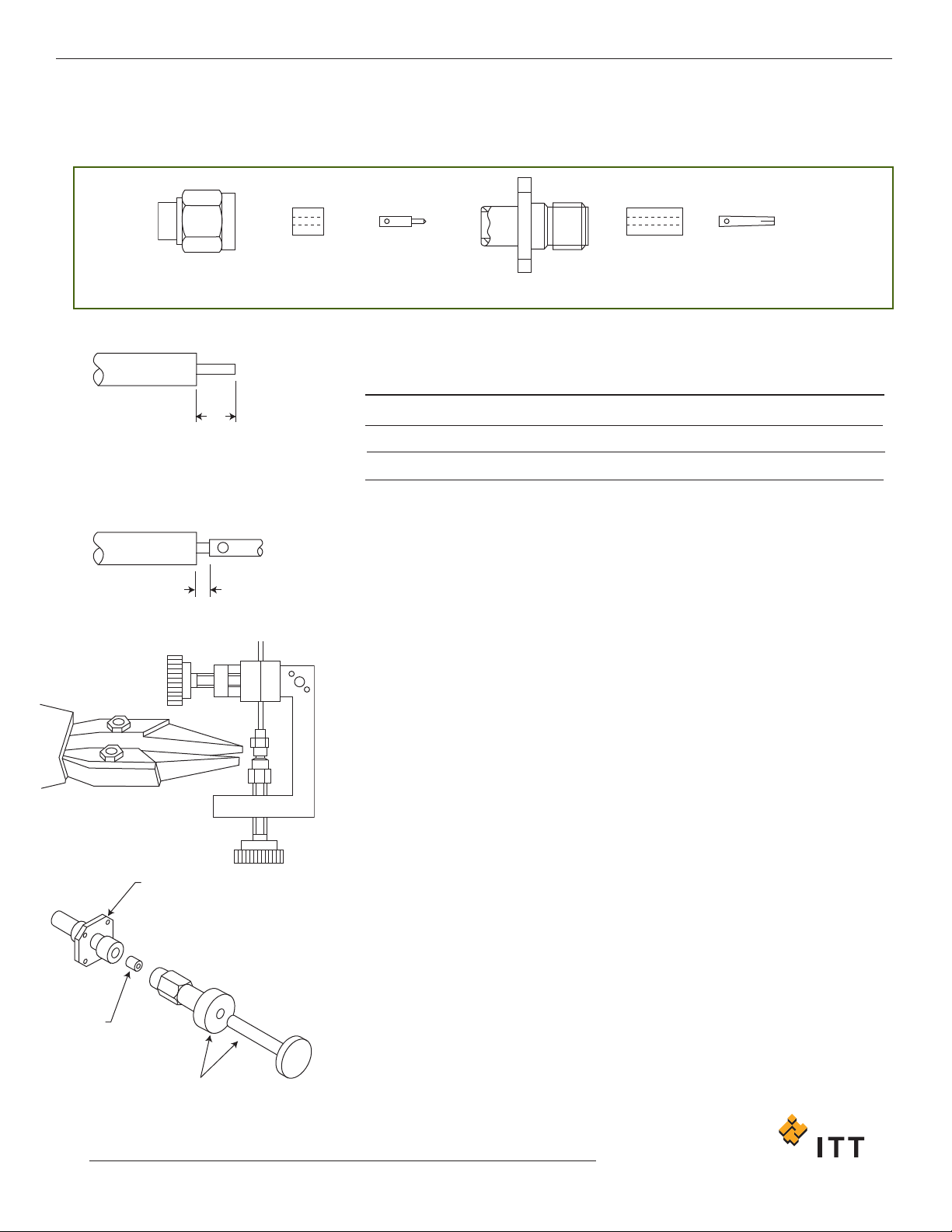
AAII--225522 && AAII--227788 SSMMAA SSttrraaiigghhtt CCoonnnneeccttoorrss,, DDiirreecctt SSoollddeerr
((SSeeppaarraattee CCeenntteerr CCoonnttaacctt)) TTyyppee ffoorr SSeemmii--RRiiggiidd CCaabbllee
PLUG BODY INSULATOR CONTACT JACK BODY INSULATOR CONTACT
A
B
CONNECTOR
INSULATOR
DIELECTRIC
INSERTING TOOL
1. Cut cable end square. Trim the cable outer conductor and dielectric as
shown taking care not to nick the center conductor. Deburr outer conductor at
point of cut.
2. Tin center conductor (DO NOT OVER TIN).
3. Solder contact to center conductor ensuring that dimension shown is
maintained. Remove any excess solder.
4. Clean housing area of outer conductor with abrasive paper and clean in a
suitable agent.
5. Place connector assembly in Assembly Jig T1848, or other suitable clamping
arrangement, with contact in locator tool as shown.
Tighten screw to secure cable between inserts then tighten locator to seat cable
firmly. Place solder ring around cable adjacent to connector body and heat the
connector body using an appropriate heat source (solder tongs with variable
control). Apply sufficient heat for solder to flow but using minimum heat cycle.
6. Using dielectric insertion Tool T2508 (for plugs) or T2509 (for jacks), press
insulator into body
. Assembly is now ready for use.
N.B. Various body configurations can apply.
Assembly Instruction No.
AI-252
AI-278
Configuration
Plug
Jack
A
3,18 +/- 0,25 (.125 +/- .010)
2,54 +/- 0,25 (.100 +/- .010)
B
0,38 (.015)
0,38 (.015)
Cannon 50 Ohm Connectors ASSEMBLY INSTRUCTIONS
47
www.ittcannon.com
Dimensions shown in mm (inch)
Specifications and dimensions subject to change
STEP 1 - 2
STEP 3
STEP 5
STEP 6
Cannon 50 Ohm Connectors ASSEMBLY INSTRUCTIONS
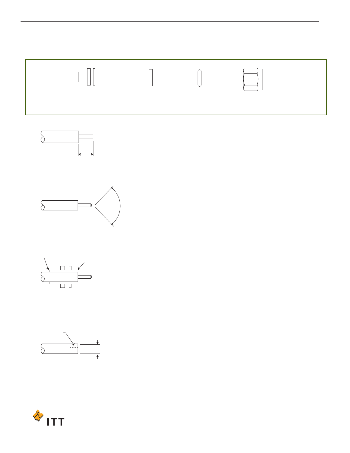
AAII--330022 SSMMAA SSttrraaiigghhtt CCoonnnneeccttoorrss,, DDiirreecctt SSoollddeerr ((CCaabbllee CCoonndduuccttoorr
uusseedd aass CCeenntteerr CCoonnttaacctt)) TTyyppee ffoorr SSeemmii--RRiiggiidd CCaabbllee
COUPLING
NUT
INTERFACE
SEAL
RETAINING
RING
BODY
A
90º±5º
SOLDER RING
BODY END FLUSH
WITH CABLE
ø1,04 ± 0.05
(.041 ± .002)
2,79 (.110)
MIN DEEP
ø4,62
(.182)
MIN
DIELECTRIC
COMPRESSION TOOL
X
1. Trim the cable outer conductor and dielectric as shown taking care not to nick
the center conductor. Deburr outer conductor at point of cut.
2. Point the end of the center conductor using a miniature file.
3. If style - 9073 is being assembled slip the coupling nut onto the cable.
4. Clean housing area of outer conductor with abrasive paper and clean in a
suitable agent. Place 24 s.w.g. soldering ring and connector body on prepared
end of cable. Ensure body is correct way round. End of cable to be flush with
end of connector body as shown.
5. Compress expanded dielectric back into cable outer conductor with Dielectric
Compression Tool as shown, until it is flush with end of body and outer
conductor.
6. Fit the interface seal.
7. Install the spring retaining ring, compress with Tool T0557/1 and fit the
coupling nut.
A = 2,16 +/- 0,13 (.085 +/- .005)
48
www
.ittcannon.com
Dimensions shown in mm (inch)
Specifications and dimensions subject to change
STEP 2
STEP 1
STEP 4
STEP 5
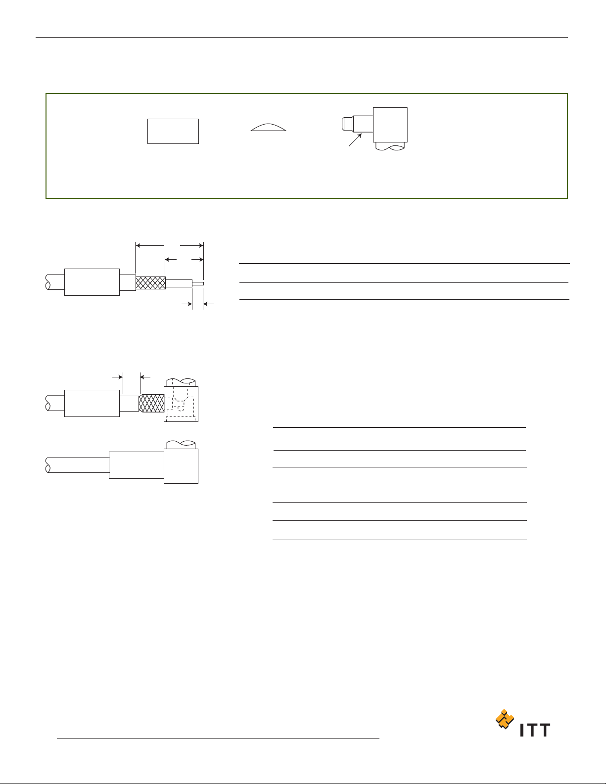
BBAAII--001155 SSMMBB RRiigghhtt AAnnggllee CCoonnnneeccttoorrss,, CCrriimmpp TTyyppee ffoorr BBrraaiiddeedd CCaabbllee
C
RIMP FERRULE CAP BODY
TUBULAR
E
XTENSION
C
1,50 (,059) SLIT (2)
180º APART (OPTIONAL)
B
A
1. Trim cable to dimensions shown taking care not to nick braid or center
conductor. Tin center conductor (DO NOT OVER TIN) then slip crimp ferrule
over cable.
2. Insert trimmed cable into back end of body. The tubular body extension will
slide under the braid with the rear portion of extension fitting under the
jacket as shown. The center conductor will extend into slot in contact.
NOTE: On smaller diameter cables, two longitudinal slits in the jacket, 180˚
apart, may be cut to ease assembly.
3. Slip ferrule up over braid to face of square body and crimp, using Cannon’s
Crimp Tool and suitable Die Set (see table).
4. Using a small soldering iron solder center conductor to contact. NOTE: The
center conductor should not protrude beyond the contact to touch the body.
Solder should not protrude beyond the slotted section of the contact.
5. Locate the cap in rear of body and dimple or lightly punch to ensure it is
locked in position. (A flat punch is recommended). SUPPORT BODY ON
SHOULDER DURING THIS OPERATION.
Only common cable retention features are shown in detail. Various body
configurations can apply.
Assembly Instruction No.
BAI-015
A
10,00 (.393)
B
4,00 (.157)
C
1,50 (.059)
Cable Numbers
RG142/U
RG196/U
RG316/U
RG316/U
RD316
Cable Code
9052
3196
0000
3188
9399
Die Size
5,41 (.213)
2,67 (.105)
3,25 (.128)
3,25 (.128)
3,84 (.151)
Die Set
K29265
K29263
K29263
K29263
T1025/9
Cannon 50 Ohm Connectors ASSEMBLY INSTRUCTIONS
49
www.ittcannon.com
Dimensions shown in mm (inch)
Specifications and dimensions subject to change
STEP 3
STEP 2
STEP 1