ITT-Cannon-RF50-Catalog.pdf - 第43页
A A I I - - 1 1 0 0 2 2 & & A A I I - - 2 2 3 3 6 6 S S M M A A S S t t r r a a i i g g h h t t C C o o n n n n e e c c t t o o r r s s , , C C r r i i m m p p T T y y p p e e f f o o r r B B r r a a i i d d e e …
Cannon 50 Ohm Connectors ASSEMBLY INSTRUCTIONS
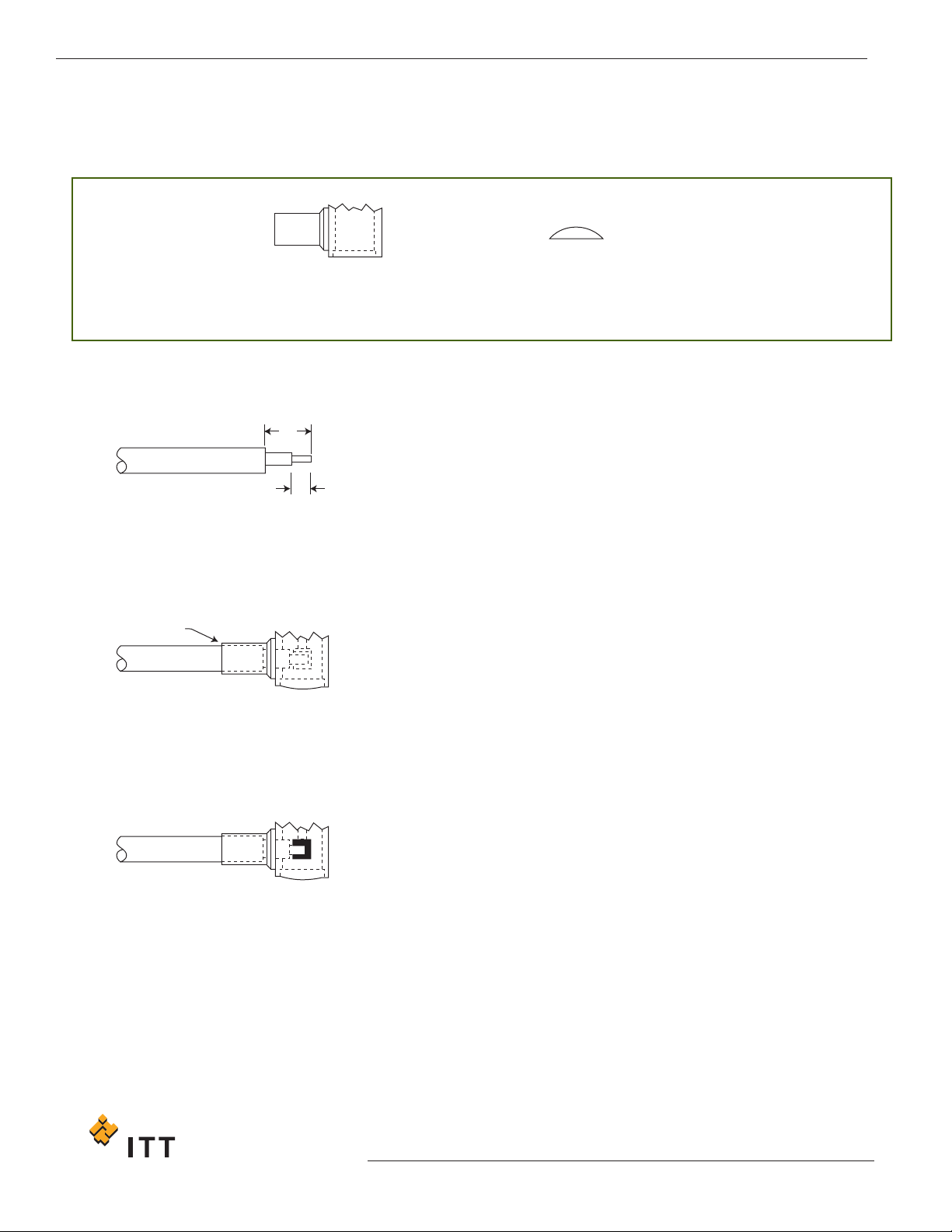
AAII--9988 SSMMAA RRiigghhtt AAnnggllee CCoonnnneeccttoorrss,, DDiirreecctt SSoollddeerr TTyyppee ffoorr
SSeemmii--RRiiggiidd CCaabbllee
BODY ASSEMBLY CAP
B
A
SOLDER
1. Trim cable jacket, dielectric and center conductor to dimensions
shown, being careful not to fracture the center conductor. Tin center
conductor (DO NOT OVER TIN).
2. Slide cable into body and solder into place.
3.
Solder center conductor to contact (do not over solder), then locate
the cap in rear of body and dimple or lightly punch to ensure it is
locked in position.
.
A = 4,75 +/- 0,13 (.187 +/- .005)
B = 2,29 +/- 0,13 (.097 +/- .005)
42
www
.ittcannon.com
Dimensions shown in mm (inch)
Specifications and dimensions subject to change
STEP 1
STEP 2
STEP 3
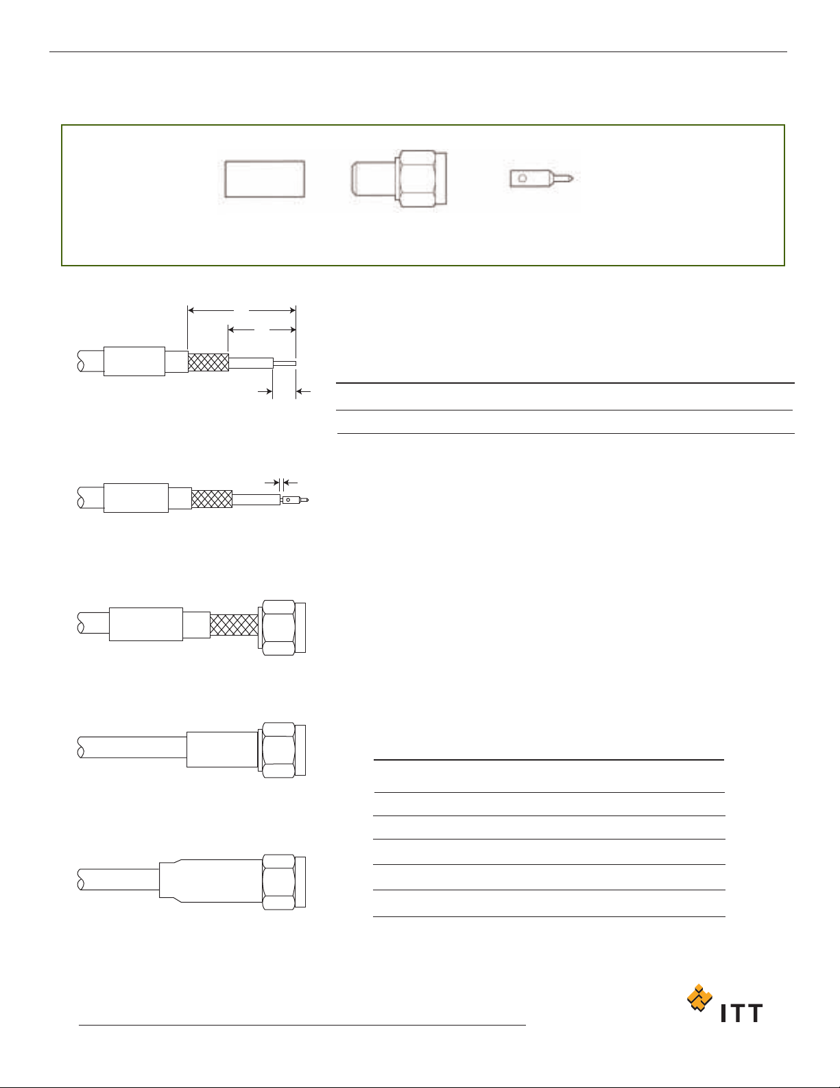
AAII--110022 && AAII--223366 SSMMAA SSttrraaiigghhtt CCoonnnneeccttoorrss,, CCrriimmpp TTyyppee ffoorr
BBrraaiiddeedd CCaabbllee
0,38
(.015)
C
B
A
1. Trim cable to dimensions shown being careful not to nick the braid or
center conductor. Tin center conductor, (DO NOT OVER TIN) then slip
ferrule (and shrink tubing if supplied) over cable.
2. Solder center conductor to contact. With AI-102 and AI-236 the gap
shown is to be maintained.
3. Insert trimmed cable into the rear of the body assembly. Tubular
body extension will slide under the braid with the rear portion of
extension fitting under the jacket as shown. NOTE: When using
cables with inflexible jackets it is permissible to make two 3,17 (.125)
long longitudinal slits in the outer jacket.
4. Slide ferrule flush against the body and crimp in position using
Cannon’s Crimp T
ool and suitable Die Set (see table).
5.
Slide heat shrinkable tubing over ferrule and apply heat until tubing
shrinks down.
Assembly Instruction No.
AI-102 & AI-236
A
10,31 (.406)
B
4,37 (.172)
C
2,77 (.109)
Cable Numbers
RG141/U
RG142/U
RG188/U
RG196/U
RD316
Cable Code
9141
9142
9188
9196
9399/9875
Die Size
5,42 (.213)
5,42 (.213)
3,25 (.128)
2,67 (.105)
3,84 (.151)
Die Set
K29265
K29265
K29263
K29263
T1025/9
Cannon 50 Ohm Connectors ASSEMBLY INSTRUCTIONS
43
www.ittcannon.com
Dimensions shown in mm (inch)
Specifications and dimensions subject to change
STEP 1
STEP 2
STEP 3
STEP 4
STEP 5
CRIMP FERRULE BODY ASSEMBLY CONTACT
Cannon 50 Ohm Connectors ASSEMBLY INSTRUCTIONS
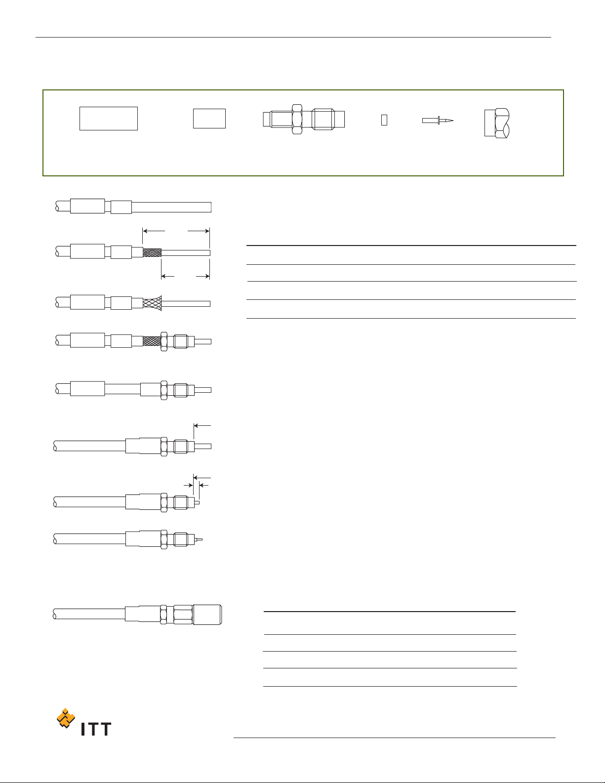
AAII--112288 && AAII--666633 SSSSMMBB // SSSSMMCC SSttrraaiigghhtt CCoonnnneeccttoorrss,, CCrriimmpp TTyyppee ffoorr
BBrraaiiddeedd CCaabbllee
HEAT
SHRINKABLE
TUBING
CRIMP
FERRULE
REAR BODY REAR
INSULATOR
CONTACT FRONT
BODY
D
B
A
A
C
SURFACE
SURFACE
1. Slide heat shrinkable tubing and ferrule on to cable.
2. Trim cable to dimensions shown:
3. Slide rear body over dielectric and under the braid until braid is flush with
flange. N.B. When using cable with inflexible jackets it is permissible to
make two 3,00 (.118) long longitudinal slits in the outer jacket.
4. Slide ferrule over exposed braid up to hex. flange.
5. Crimp using Cannon’s Crimp Tool and suitable Die Set (see table). Ensure
ferrule is held close to hex. flange.
6. Slide heat shrinkable tubing over crimp and heat shrink into place using hot
air gun. Air temperature should be approximately 125˚C.
7. Trim dielectric flush with surface “A” on body using a sharp knife. Take care
not to nick center conductor.
8. Trim center conductor as shown.
9. Tin center conductor (do not allow solder to touch end of body or dielectric).
10. Place a small solder preform made from 0,26 - 0,31 (.010 - .012) dia.
(28 swg) multi-core solder in rear of contact.
11. Place rear insulator over center conductor. When insulator has counterbore,
the contact fits into the counterbore.
12. Assemble contact onto center conductor, heat to make solder connection.
Do not allow solder to protrude outside spill hole.
13.
Solder should be visible at inspection hole, if excess solder runs from
inspection hole, remove with sharp blade taking care not to damage plating.
14. Screw on the front body and tighten to a torque of 0.14Nm (20 in. ozs)
Only common cable retention features are shown in detail.
Various body configurations can apply.
Assembly Instruction No.
AI-663
AI-128 for center conductors ø 0.51 (.020)
AI-128 for all other conductor sizes
B
6,86 (.270)
6,76 (.266)
7,54 (.297)
C
2,29 (.090)
2,29 (.090)
3,05 (.120)
D
10,41 (.410)
9,53 (.375)
10,31 (.406)
Cable Numbers
RG196/U
RG316/U
RD316
Cable Code
3196
3188
3875
Die Size
2,67 (.105)
3,25 (.128)
3,84 (.151)
Die Set
K29263
K29263
T1025/9
44
www
.ittcannon.com
Dimensions shown in mm (inch)
Specifications and dimensions subject to change
STEP 1
STEP 2
STEP 3
STEP 4
STEP 7
STEP 8
STEP 12
STEP 14