ITT-Cannon-RF50-Catalog.pdf - 第28页
ELECTRICAL I mpedance Frequency Range V oltage Rating Insulation Resistance Contact resistance Contact Current Rating 50 Ω SSMB = 0 to 4.0 GHz. SSMC = 0 to 12.4 GHz At Sea Level = 250 Vrms. at 21km (70k feet) = 60 Vrms 1…
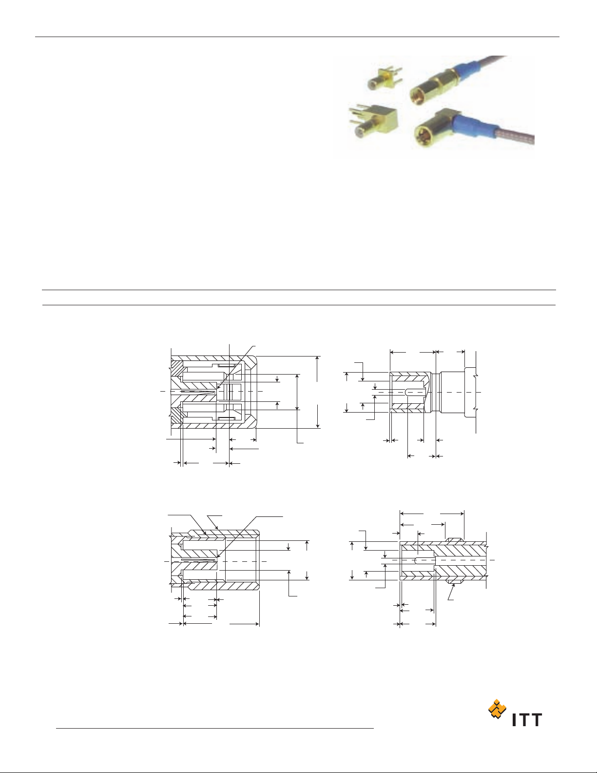
This range of 50 ohm microminiature radio frequency
connectors is suitable for both military and commercial
equipment operating at frequencies up to 4 GHz (SSMB)
a
nd 12.4 GHz (SSMC). They provide a choice of Snap-on
(SSMB) or Screw-on (SSMC) and are available for a wide
range of flexible cables.
SSMC connectors are used where a positive mechanical
engagement is required and where space permits the
use of torque wrenches. SSMB connectors are quick
disconnect versions of the SSMC and are used in
applications where limited space prohibits the use of
torque wrenches or when components or modules must
be quickly changed to keep down time to a minimum.
NOTES
1) Inside diameter of female contact to meet VSWR, mating characteristics and
connector durability
, when mated with a 0,36 - 0,38 (.014 - .015) diameter male
contact.
2) Must meet the force to engage and
disengage when mated with its
mating part.
0,84
(.033)
MIN
0,00
(.000)
MIN
RP
PLUG JACK
1,78
(.070)
MAX
0,84
(.033)
MIN
SEE NOTE
# 2
Ø1,35
(.053)
MAX
Ø4,83
(.190)
MAX
Ø1,37
(.054)
MIN
Ø2,67
(.105)
MAX
Ø0.36/0.38
(.014/.015)
0,00
(.000)
MIN
0,84
(.033)
MAX
RP
1,91
(.075)
MIN
1,91
(.075)
MIN
CLOSED ENTRY CONTACT
3,10
(.122)
3,10
(.122)
MIN
0,00
(.000)
MIN
6,40 UNF-2B
THREAD
3,96
(.156)
A/F HEX
2,29
(.090) MAX
2,29
(.090)
MIN
2,29
(.090)
MIN
6,40 UNF-2A
THREAD
2,29
(.090) MAX
5,08
(.200) MAX
Ø1,35
(.053)
MIN
Ø2,57
(.101)
MIN
Ø1,37
(.054)
MIN
Ø2,54
(.100)
MAX
Ø 0,36/0,38
(.014/.015)
4,32
(.170)
MIN
3,00
(.118)
0,84
(.033)
MAX
0,00
(.000)
MIN
0,00
(.000)
MIN
JACKPLUG
RP
RP
CLOSED ENTRY
CONTACT
SSMB (SNAP-ON)
SSMC (SCREW-ON)
MMAATTIINNGG IINNTTEERRFFAACCEE
Cannon 50 Ohm Connectors SSMB / SSMC
27
www.ittcannon.com
Dimensions shown in mm (inch)
Specifications and dimensions subject to change
Key Features
• Small size
• Low mass
• Close packing density
• Used in airborne applications
ELECTRICAL
I
mpedance
Frequency Range
Voltage Rating
Insulation Resistance
Contact resistance
Contact Current Rating
50Ω
SSMB = 0 to 4.0 GHz. SSMC = 0 to 12.4 GHz
At Sea Level = 250 Vrms. at 21km (70k feet) = 60 Vrms
1000 MΩ minimum
Center Contact = 4.0 m Ω maximum initial. 6.0 m Ω maximum after environment
O
uter Contact = 1.0 m Ω maximum initial. 1.5 m Ω maximum after environment
Braid to Body = 1.0 m Ω maximum
1.0 A dc maximum
0.30 dB maximum @ 1.5 GHz
SSMB = -40 dB minimum @ 2 - 3 GHz
SSMC = -50 dB minimum @ 2 - 3 GHz
Connector Configuration
SSMB SSMC
Cable group Straight Right Angle Straight Right Angle
RG178/U, 196/U 1.25 + .02F 1.25 + .03F 1.20 + .02F 1.20 + .03F
RG188/U, 316/U 1.30 + .02F 1.30 + .03F 1.25 + .03F 1.30 + .02F
SSMB: Initial = 26.7 N (6 lbs.) max. engagement and 8.9 N(2 lbs.) minimum disengagement.
After 500 matings = 26.7 N (6 lbs.) max. engagement and 4.4 N (1 lb.) min. disengagement.
SSMC: 0.11 Nm (16 in. oz.) torque max.
SSMB: N/A SSMC: 0.2 Nm to 0.23 Nm (28 - 32 in.oz)
0.28 Nm to 0.35 Nm (40 - 50 in. oz)
SSMB: N/A SSMC: 111 N (25 lbs. ) minimum
Body , Body Components: Brass, half hard. Male and Female Contacts: Beryllium Copper.
Insulators: PTFE. Lockwashers: Phosphor Bronze. Crimp Ferrule: Annealed copper alloy.
Center Contacts: Gold plated. Other Metal Parts: Gold or nickel plated to meet the
finish and corrosion requirements of MIL-C -39012
-65° C to 165° C
MIL-STD -202, Method 101, test condition B, 5% salt solution
MIL-STD-202, Method 204, SSMB: test condition B (15 G's). SSMC: test condition D (20 G's)
MIL-STD -202, Method 213, SSMB: test condition B, 75 G's @ 6 milliseconds, 1/2 sine.
SSMC: test condition C, 100 G's @ 6 milliseconds, 1/2 sine.
MIL
-STD
-202, Method 107, test condition B, except high temperature shall be 85º C.
High temperature shall be 200ºC for connectors using 200ºC cables.
500 matings minimum
8,9 N (2 lbs.) minimum axial force.
When properly assembled to the compatible single braided coaxial cable, the retention
is equal to the breaking strength of the cable.
Body plating options
The following part number suffices can be specified for SSMB and SSMC connectors.
...220 gold body
...910 nickel body
Insertion Loss
RF Leakage
Voltage Standing Wave Ratio (VSWR)
To 12.4 GHz or 80% of upper cut-off
frequency of the cable, whichever is lower.
Applicable to 50
Ω cables only.(F = GHz)
Engagement Forces
Mating Torque
Locknut Torque
Coupling Nut Retention
Materials
Finish/Plating
Temperature Rating
Corrosion (salt spray)
Vibration, High F
requency
Shock
Thermal Shock
Connector Durability
Contact Captivation
Cable Retention
MECHANICAL
ENVIRONMENTAL
GENERAL
SSPPEECCIIFFIICCAATTIIOONNSS
Cannon 50 Ohm Connectors SSMB / SSMC
www
.ittcannon.com
Dimensions shown in mm (inch)
Specifications and dimensions subject to change
28
Mounting Plan U (P
age 40)
Mounting Plan U (Page 40)
Assembly Instructions AI-128 (Page 44)
Assembly Instructions
051 - 424 - 3188220 AI 663 (Page 44)
A51 - 424 - 3196220 AI 128 (Page 44)
Assembly Instructions
A51 - 428 - 3188220 AI 129 (Page 45)
A51 - 428 - 3196220 AI 696 (Page 45)
A51 - 428 - 3875220 AI 696 (Page 45)
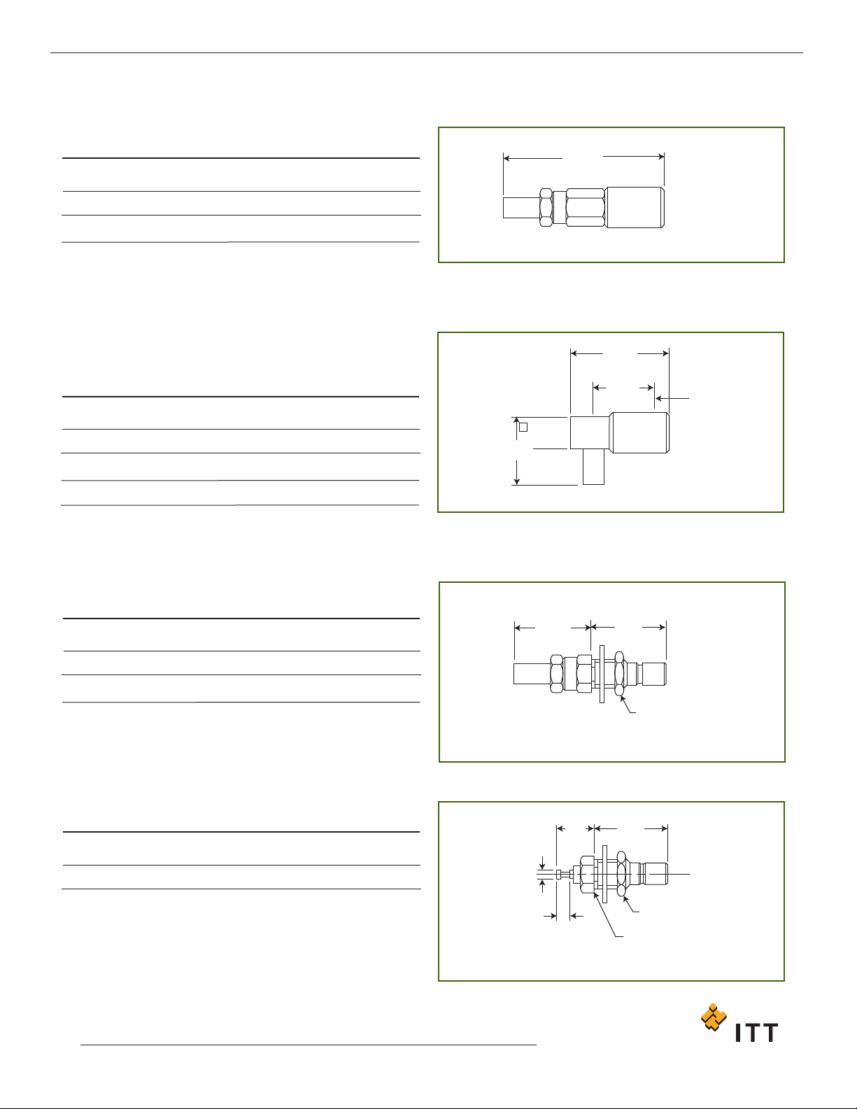
Straight Plug
Part Number
051 - 424 - 3188220
A51 - 424 - 3196220
Cable Numbers
RG174/U, 316/U
RG178/U, 196/U
A
20,01 (.790)
19,33 (.761)
A MAX
Right Angle Plug
Part Number
A51 - 428 - 3188220
A51 - 428 - 3196220
A51 - 428 - 3875220
Cable Numbers
RG174/U, 316/U
RG178/U, 196/U
RD316
A
9,55 (.376)
9,55 (.376)
10,16 (.400)
1
2,19
(.480)
MAX
7,62
(.300)
MAX
RP
3,96
(.156)
A
MAX
Bulkhead Jack
Part Number
051 - 427 - 3188220
A51 - 427 - 3196220
Cable Numbers
RG174/U, 316/U
RG178/U, 196/U
A
9,93 (.391)
10,41 (.410)
A MAX
9,12
(.359)
4,75
(.187)
A/F HEX
Bulkhead Receptacle - Rear Mount
Mounting Nut Outside Panel
Part Number
051 - 443 - 0000220
9,20
(.382)
MAX
3,99
(.157)
Ø0.91
(.036)
2,03
(.080)
4,75
(.187)
A/F HEX
3,96
(.156)
A/F HEX
PPLLUUGGSS,, JJAACCKKSS AANNDD RREECCEEPPTTAACCLLEESS
Cannon 50 Ohm Connectors SSMB
29
www.ittcannon.com
Dimensions shown in mm (inch)
Specifications and dimensions subject to change