ITT-Cannon-RF50-Catalog.pdf - 第55页
55 C C S S M M A A 3 3 - - S S M M A A S S t t r r a a i i g g h h t t C C o o n n n n e e c c t t o o r r s s , , D D i i r r e e c c t t S S o o l l d d e e r r ( ( C C a a b b l l e e C C o o n n d d u u c c t t o o r…
SOLDER
54
www
.ittcannon.com
Cannon 50 Ohm Connectors ASSEMBLY INSTRUCTIONS
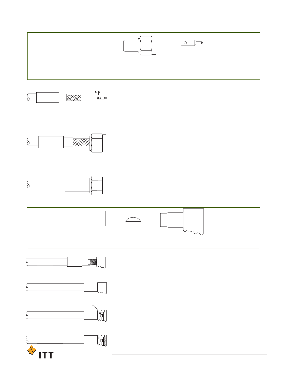
CCSSMMAA 11 -- SSMMAA SSttrraaiigghhtt CCoonnnneeccttoorrss,, CCrriimmpp TTyyppee ffoorr BBrraaiiddeedd CCaabbllee
CRIMP FERRULE BODY ASSEMBLY CONTACT
NOTE: Other body configurations apply
0,38
(.015)
1. Slide ferrule on to cable.
2. Trim cable dimension shown next to the applicable connector
drawing on page 15 or page 16.
3. Solder contact attachment:
Solder contact to inner conductor.
Crimp contact attachment:
Crimp contact to inner conductor using Cannon’s Hand Tool T4897
with positioner T4898 (for male contacts) and T4899 (for female
contacts).
4. Insert trimmed cable into the rear of the body assembly. Tubular
body extension will slide under the braid with the rear portion of
extension fitting under the jacket as shown. NOTE: When using
cables with inflexible jackets it is permissible to make two 3.17 (.125)
long longitudinal slits in the outer jacket.
5. Slip ferrule flush against the body and crimp in position using
Cannon’s Crimp Tool and Suitable Die Set (see table on page 58).
CCSSMMAA 22 -- SSMMAA RRiigghhtt AAnnggllee CCoonnnneeccttoorrss,, CCrriimmpp TTyyppee ffoorr BBrraaiiddeedd CCaabbllee
CRIMP
FERRULE
CAP BODY ASSEMBLY
1. Slide ferrule on to cable.
2.
T
rim cable dimension shown next to the applicable connector
drawing on page 15.
3. Tin center conductor (DO NOT OVER TIN).
4.
Slide body over cable dielectric and under the braid until braid is flush
against underside of body. Ensure center conductor is is located in
the forked end of the contact. NOTE: When using cables with
inflexible jackets it is permissible to make two 3.17 (.125) longitudinal
slits in the outer jacket.
5.
Slide ferrule flush against the body and crimp in position using
Cannon’s Crimp Tool and Suitable Die Set (see table on page 58).
6. Using a small soldering iron solder center conductor to contact.
NOTE: The center conductor should not protrude beyond the contact
or touch the body. Solder should not protrude beyond the slotted
section of the contact.
7.
Locate the cap in rear of body and press flush to outer body to
ensure it is locked in position.
STEP 1 - 3
STEP 5
STEP 4
STEP 6
STEP 5
STEP 1 - 4
STEP
7
55
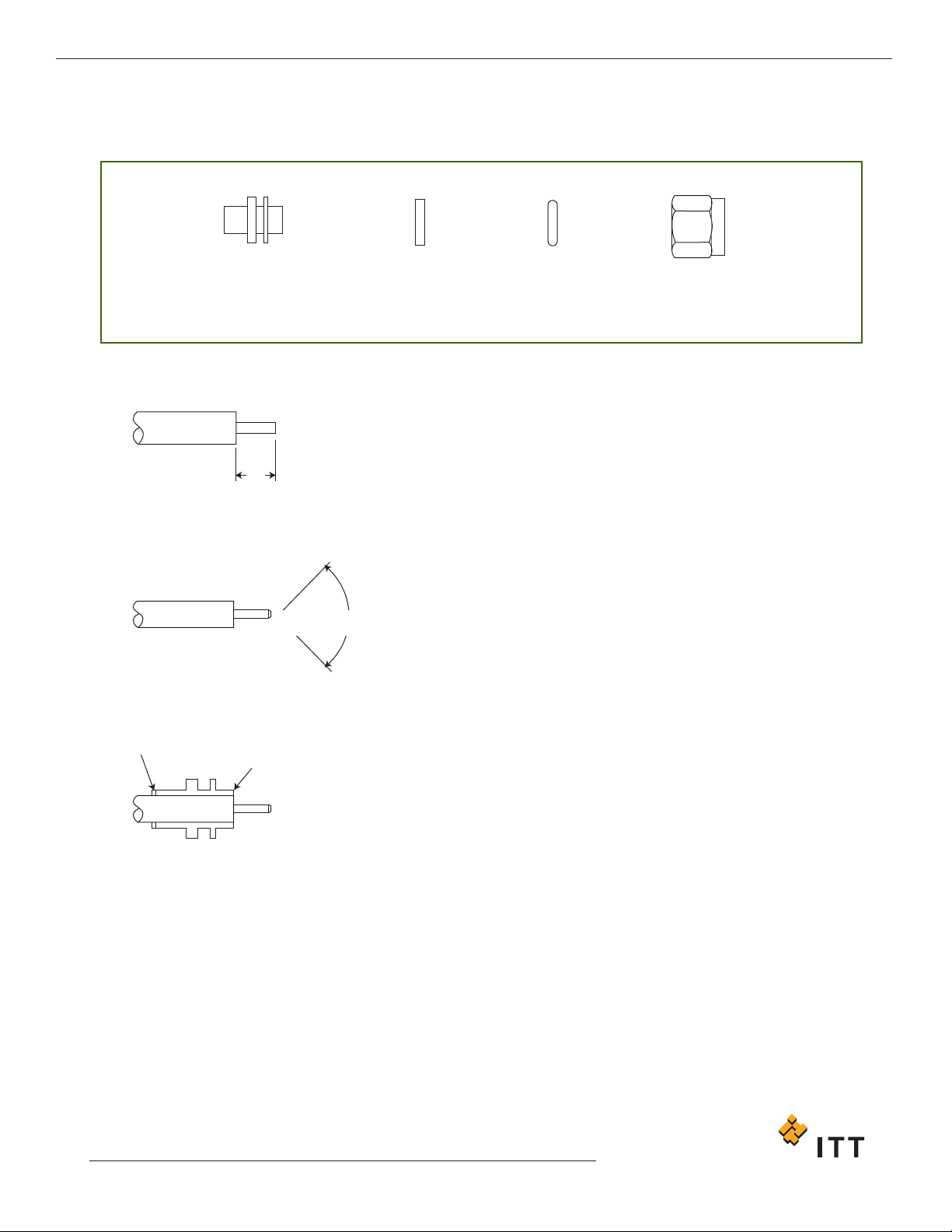
CCSSMMAA 33 -- SSMMAA SSttrraaiigghhtt CCoonnnneeccttoorrss,, DDiirreecctt SSoollddeerr
((CCaabbllee CCoonndduuccttoorr uusseedd aass CCeenntteerr CCoonnttaacctt)) TTyyppee ffoorr SSeemmii--RRiiggiidd CCaabbllee
COUPLING
NUT
INTERFACE
SEAL
RETAINING
RING
BODY
1. Remove the cable outer conductor and dielectric to the dimension
shown taking care not to nick the center conductor using cable
cutting tool. Deburr outer conductor at point of cut.
2. Point the end of the center conductor using a miniature file or
suitable tool.
3. Clean housing area of outer conductor with abrasive paper and clean
in a suitable agent. Ensure body is correct way round. Solder body
ensuring end of cable to be flush with end of connector body as
shown.
4. Fit the interface seal.
5. Install the spring retaining ring, compress with circlip pliers and fit
the coupling nut.
2,3
(.091)
90˚+/- 5˚
Solder ring
Body end flush
with cable
Cannon 50 Ohm Connectors ASSEMBLY INSTRUCTIONS
STEP 3
STEP 2
STEP 1
www.ittcannon.com
Dimensions shown in mm (inch)
Specifications and dimensions subject to change
56
www
.ittcannon.com
Dimensions shown in mm (inch)
Specifications and dimensions subject to change
Cannon 50 Ohm Connectors ASSEMBLY INSTRUCTIONS
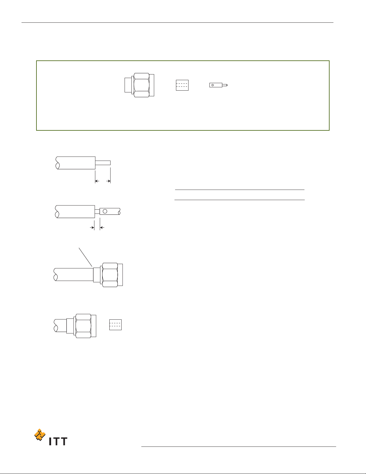
CCSSMMAA 44 -- SSMMAA SSttrraaiigghhtt CCoonnnneeccttoorrss,,
DDiirreecctt SSoollddeerr ((SSeeppaarraattee CCeenntteerr CCoonnttaacctt)) TTyyppee ffoorr SSeemmii--RRiiggiidd CCaabbllee
PLUG BODY INSULATOR CONTACT
SOLDER
A
B
1. Cut cable end square. Remove the cable outer conductor and
dielectric to the dimension shown taking care not to nick the center
conductor
. Deburr outer conductor at point of cut.
2. Tin center conductor. (DO NOT OVER TIN)
3. Solder contact to center conductor ensuring that the dimension
shown is maintained. Remove any excess solder.
4. Clean housing area of outer conductor with abrasive paper and clean
in a suitable agent.
5. Clamp the connector assembly in a suitable fixture. Ensure that the
contact is in the correct interface position. Place soldering ring
around cable adjacent to connector body and heat the connector
body using an appropriate heat source. Apply sufficient heat for
solder to flow but using minimum heat cycle.
6.
Using dielectric insertion T
ool T2508, press insulator into body
.
Assembly is now ready for use.
A
3.18 +/- 0.25 (.125 +/- .010)
B
0.38 (.015)
STEP 6
STEP 5
STEP 3
STEP 1