00196645-02_JG_ CP20P CP20A CPP TWIN HEAD Nozzles_en.pdf - 第14页
1 - 10 www.asm-smt.com Correct Assignment of Nozzle – Component for SIPLACE C&P and SIPLACE CPP To prevent any detection problems with small structures, the component must be in the focus range (area of focus) of the…
1 - 9
www.asm-smt.com
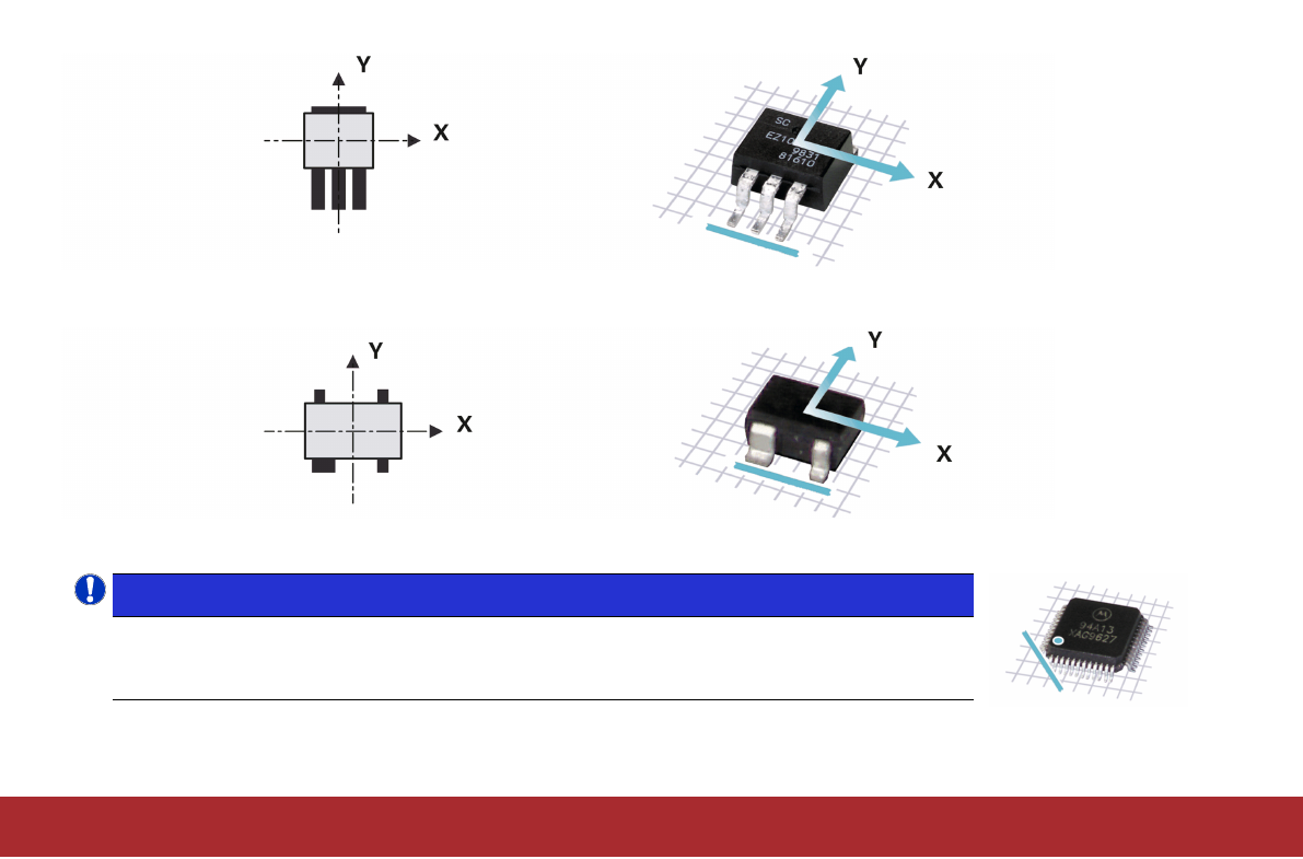
Rule 3: The side with the most leads is at the bottom.
Rule 4: If the component has a special feature, such as a wider lead, this special feature will be at the bottom.
Rule 1 has top priority, followed by rules 2, 3 and 4.
NOTICE!
The sample components at the beginning of each chapter are shown in accordance with
these four rules. The marking on the adjacent example shows the bottom left corner of
the component.
.
1 - 10
www.asm-smt.com
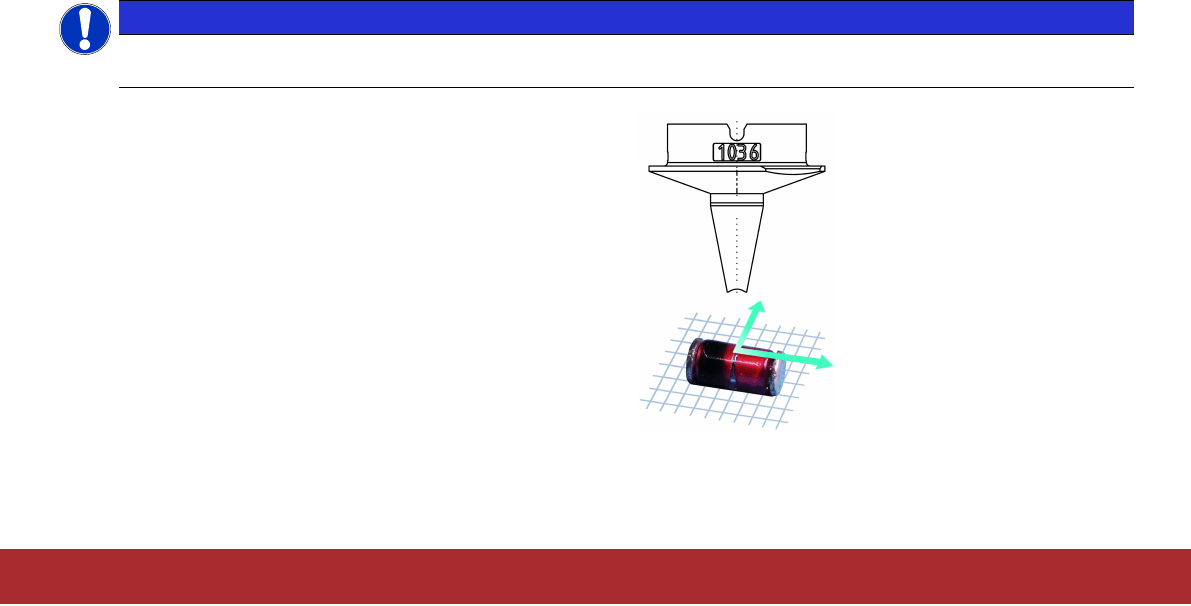
Correct Assignment of Nozzle – Component for SIPLACE C&P and SIPLACE CPP
To prevent any detection problems with small structures, the component must be in the focus range (area of focus) of the
camera.
The focus range of the SIPLACE C&P20 camera is between 9.4 and 11.4 mm (i.e. 10.4 +/– 1 mm).
The focus range of the SIPLACE CPP is between 13.3 and 17.3 mm (i.e. 15.3 +/– 2 mm).
NOTICE
When selecting the correct nozzle for a component, check whether the total value of nozzle length plus compon-
ent height is within this range.
Example:
Nozzle length L = 9.400 mm
Component height H = 1.200
mm
Total = 10.600 mm
1 - 11
www.asm-smt.com
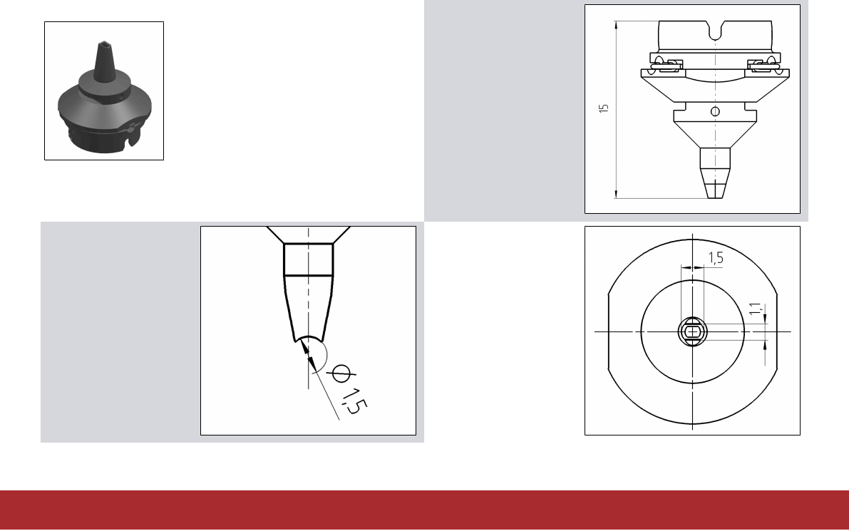
Nozzle Descriptions
Example:
L = 15.000 mm
r
tip
= 0.750 mm
Tip: 1.500 x 1.100 mm (LxW)
L shows the nozzle
length from the base
to the tip.
r
tip
shows the radius
of the nozzle tip for
cylindrical
components.
Example:
r
tip
= Ø 1.5 mm / 2
= 0.750 mm
Tip shows the length
and width or the
diameter of the
nozzle tip.