IFS-NX_SPE_EN.pdf - 第14页
IFS - NX P rodu ct S pecificat ions 10 4-4-3 Second medi um - scale c onfiguration (number of co nnected m achine s: 26 to 35) When you op erate the second med i um - s cale system t o w hich 26 to 35 m achin es are conn…
IFS-NX Product Specifications
9
System configuration
Each machine is connected to the IFS-NX system via a Local Area Network (LAN).
The number of IFS servers required to operate IFS-NX varies depending on the number of connected
machines.
* Since an FX-3/3R/3RA or an RX-7/7R has two stations, each of these machine is counted as two
machines.
You can install an IFS client and a server on the same PC also when you configure the system as
shown below. In this case, such a PC should conform to the specifications of a PC for an IFS
server.
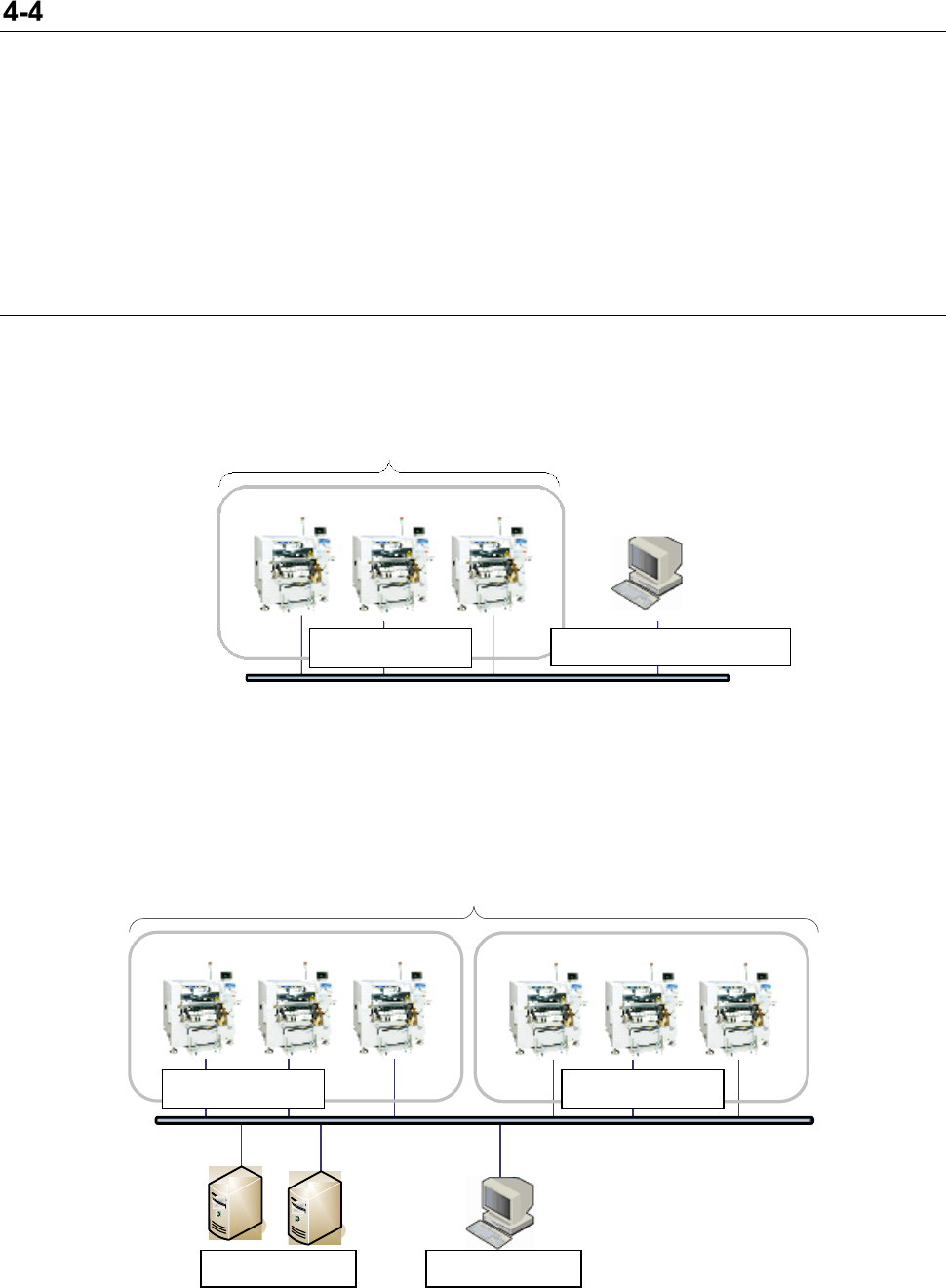
4-4-1 Example of a small-scale system configuration (number of the connected
machines: 1 to 10)
When you operate a small-scale system to which 1 to 10 machines are connected, one IFS server is
required. In the system configuration example below, an IFS server and a client are installed on the
same PC.
* The maximum number of machines that can be connected to the system is 10.
Figure 4-4-1-1 IFS system configuration example (small-scale)
4-4-2 Example of a medium-scale configuration (number of the connected machines: 11 to 25)
When you operate a medium-scale system to which 11 to 25 machines are connected, two IFS servers
are required.
* The maximum number of machines that can be connected to the system is 25.
Figure 4-4-2-1 IFS system configuration example (medium-scale)
UP to 10 machines
Production line 1
IFS client/server
UP to 25 machines
Production line 1
Production line 2
IFS server
IFS client
IFS-NX Product Specifications
10
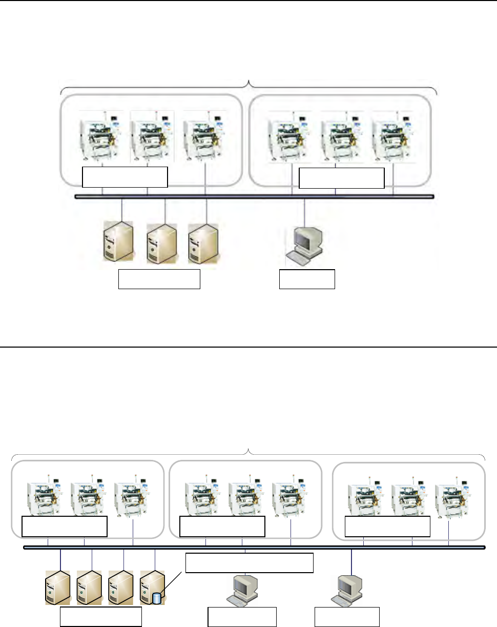
4-4-3 Second medium-scale configuration (number of connected machines: 26 to 35)
When you operate the second medium-scale system to which 26 to 35 machines are connected, three
IFS servers are required.
* The maximum number of machines that can be connected to the system is 35.
Figure 4-4-3-1 IFS system configuration example (medium-scale)
4-4-4 Large-scale configuration (number of the connected machines: 36 to 70)
When you operate a large-scale system to which 36 to 70 machines are connected, four IFS servers
are required. A large-scale configuration system requires the priced DB2 license.
* The maximum number of machines that can be connected to the system is 70.
* The DB2 priced option license is necessary for 1 unit. See 6-1 Sever PC Specification for the
details.
DB 2 LUVS
Figure 4-4-4-1 IFS system configuration example (large-scale)
IFS client
IFS client
DB2 priced option license
UP to 35 machines
Production line 1
Production line 2
IFS server
IFS client
UP to 70 machines
Production line 1
Production line 2
IFS server
Production line 3
IFS-NX Product Specifications
11
Overview of the software
List of functions
Function
Required license
Standard functions
Parts Verification
Changing the setting of the Parts Verification software
Function for displaying an incorrect feeder attachment
position on the screen (for a machine)
Component inventory control/Feeder location search
Random feeder setup
Extended functions (The license is not required for one machine
but is required for two or more machines.)
Job setup function
Job setup license
Function for displaying an incorrect feeder attachment
position on the screen (for a Client PC)
Job setup license
Extended functions (The licenses are required for all machines.)
Traceability
Traceability license
Reading a circuit barcode
Traceability license
MSD control
MSD control license
Management of feeder maintenance history
Feeder maintenance license
Connection of a general-purpose printer
- Machine license for a general-purpose printer
- Traceability license for a general-purpose
printer
Connection to a system conforming to IPC-CFX
License for adding the CFX output function
Kitting Control
Kitting Control license
Linkage with the ISM tower
License for connecting to ISM
Storage function
Storage license
Description of software function
5-2-1 Parts Verification
This is a function for preventing a defective PWB from being produced due to placement of a
component at a wrong position.
At production setup, when components run out or when tapes are spliced, an operator is supposed to
verify components to be placed on a board, and only if he/she decides that they are appropriate, the
system starts a new PWB production or continues the suspended production.
If component verification is not performed yet, production is stopped with the interlock function.
There are three kinds of methods, a barcode, an RFID, and CAN, to verify components. Moreover, they
can be used even when a barcode and RFID or a barcode and CAN are intermingled with each other in
the same machine or same bank. A CAN and RFID can be intermingled with each other only when the
electric bank is used for the CAN and MTC/MTS is used for the RFID. The RFID and CAN cannot be
intermingled with each other in the same bank.
5-2-2 Changing the setting of the Parts Verification software
If you want to exclude a particular component from the target components that are to be verified with
the Parts Verification software, you can change the setting of the Parts Verification software on the
operation panel of the mounter.
You can set the target to be verified with the Parts Verification software among a component, a bank, a
feeder type and MTC/MTS.
5-2-3 Component inventory control/Feeder location search
By registering each component when it is put in storage, you can search the component location and
the number of remaining components by serial number. This function leads rationalization of inventory
control and inventory clearance.