IFS-NX_SPE_EN.pdf - 第17页
IFS - NX P rodu ct S pecificat ions 13 5-2- 14 K itting Control (Option) Kitting Cont rol loads BOM infor mation such as a pro duction progra m , and then ent ers the number of PWBs plann ed to be produced to cr eate a b…
IFS-NX Product Specifications
12
5-2-4 Random feeder setup
This is a function for a user to place a feeder at arbitrary position and enable production.
Even when the feeder is placed at any position during an initial setup, a machine acquires the feeder
arrangement situation and updates the pick data of the production program.
5-2-5 Job setup
This software allows you to check components and their positions at offline setup with a feeder
exchange trolley before production starts to improve the production efficiency.
5-2-6 Function for displaying an incorrect feeder attachment position on the screen
When a feeder has been wrongly attached, the original correct position to place it is displayed on the
screen.
5-2-7 Splicing function
An RF feeder can use a splicing sensor to detect a spliced point on a tape. The splicing sensor is
optional. When any splicing sensor is not used, the system detects a spliced point with the specified
number of successive empty pockets.
5-2-8 Traceability (Option)
This is a function that records the serial number and lot number of the components placed on each
PWB and enables tracking of them.
A PWB code or a circuit code is read, and then preserved in the database of the IFS server as
traceability information.
This preserved information can be browsed and exported with the Reporting through a terminal that
can access to the server.
5-2-9 Reading a circuit barcode (Option)
A circuit barcode (circuit code) is a barcode or 2D code that has been stuck on each circuit of a
multi-place matrix PWB or multi-place non-matrix PWB. The traceability information can be
accumulated for every circuit by reading this circuit code and doing a production.
5-2-10 MSD (Moisture Sensitive Device) control (Option)
It is possible to prohibit the use of out-of-date MSD components according to the setting off the IS
server. This prevents the unauthorized use of out-of-date components.
5-2-11 Management of feeder maintenance history (Option)
This software controls the maintenance schedule of devices such as a feeder and a trolley, and issues
the corresponding warning.
5-2-12 Connection to a general-purpose printer (Option)
This software provides the system with the following functions: connection to a general-purpose
printer, obtaining of the production result of a general-purpose printer, and output of the result to
Reporting as the traceability information.
5-2-13 Connection to a system conforming to IPC-CFX (Option)
This software allows the IFS system to participate in a system (such as JaNets) that outputs data
externally according to IPC Connected Factory Exchange (IPC-CFX) standard.
IFS-NX Product Specifications
13
5-2-14 Kitting Control (Option)
Kitting Control loads BOM information such as a production program, and then enters the number of
PWBs planned to be produced to create a batch. It assists the operation (kitting) that collects
components required for production as a kit by assigning components whose number is sufficient for
completing of PWBs production.
5-2-15 Linkage with the ISM tower (Option)
This software updates and controls information on components required for production of PWBs
between the IFS server and the ISM tower by synchronizing the following information with the ISM
tower: information on components registered in the IFS server varying when a component is added or
deleted or when the number of remaining components changes. In addition, when the ISM server
requests the ISM tower to deliver a component, a component can be extracted at the required timing.
5-2-16 Storage function (Option)
This software can control loading/unloading of components to/from a component shelf located outside
the IFS server.
IFS-NX Product Specifications
14
Operation environment
Server PC specification
The server PC specification recommended for the IFS-NX is shown below:
- The number of PCs for the IFS servers changes according to the number of machines to be
connected to the system.
- The server operates as a database server and a Web server.
- It is also possible to install COI on a server.
It is recommended that the server PC can access the Internet.
* FX-3/3R/3RA and RX-7/7R have two stations, so one machine is converted into two machines.
6-1-1 New Installation Configuration for IFS-NX Version 8.10 or later (DB2 Ver11.5.5)
6-1-1-1 Server PC specification (the number of machines to be connected to the system: 1 to 10)
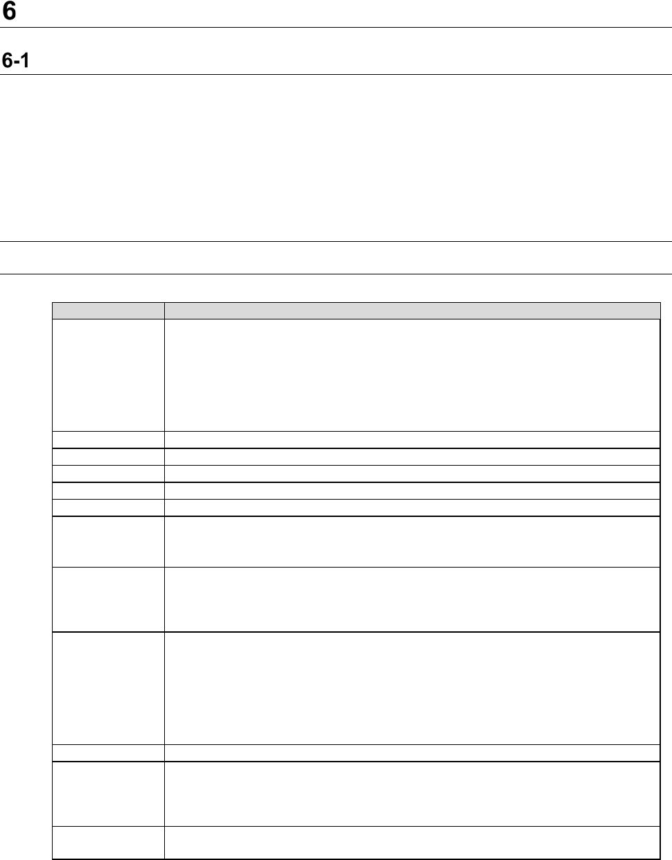
Table 6-1-1-1 Server PC specifications (Number of machine units: 1 to 10 units)
Recommended specification
Function
CGS/CGSDW/CGSCX database
Cogiscan Web Server (for Configurator, POI and installation)
Cogiscan Web Server (for Reports)
Cogiscan Web Server (for CAMX Message Broker)
Cogiscan Web Server (for Co-NECT Server)
TTC Server (for TTC-GO)
Cogiscan Data Warehousing Service
CPU
Quad Core CPU 2.00 GHz or higher (Hyper-Threading exists)
RAM
8GB or more
HDD
300GB RAID1 HDD x 2 sets *1
DVD-ROM
1 unit or more
Screen size
15-inch monitor or bigger
Interface
Standard mouse and keyboard
100BASE-TX/10BASE-T - capable, LAN connector (RJ-45) ×1
USB2.0
×
1
OS *2
Windows 10 Pro (64bit)
Windows Server 2012 R2 Standard (64bit)
Windows Server 2016 (64bit)
Windows Server 2019 Standard Edition (64bit)
Firewall
- The following ports need to be opened:
80 (Cogiscan Web Server), 7654 (Cogiscan PTU Shell Server), 50000 (IBM
DB2), 56277 (Cogiscan CIMS Server), 56278 (Cogiscan TTC Server)
- The following programs need to be opened:
\Program Files\Cogiscan\Server\Web Server\bin\cgsserver.exe
\Program Files\Cogiscan\Server\ttc\ttc.exe
\Program Files\Cogiscan\Server\ttc\orb\orb.exe
DB2
DB2 Community Edition V11.5.5 (Free)
The maximum
number of
connectable
client PCs
10 units *2
Uninterruptible
power system
Approximately 60 minutes at 100 VA, 70 W (APC Smart-UPS 700 or equivalent)
*1 Physical HDDs are 4 units in total because RAID 1 configuration requires 2 sets.
Recommended configuration is the configuration with C-Drive and D-Drive in each RAID1.
*2 JaNets/IS client using IFX-NX function is also included in the number of connecting units.