00191021-02.pdf - 第110页
3 Calibration Functions User’s Manual Test Program S ITEST 3.2 Complete Calibration of the Machine Software Version 403.xx Edition 12/97 3 - 6 Example: Calibration of the camera s and heads ● Click on t he PCB camera but…
User’s Manual Test Program SITEST 3 Calibration Functions
Software Version 403.xx Edition 12/97 3.2 Complete Calibration of the Machine
3 - 5
3.2 Complete Calibration of the Machine
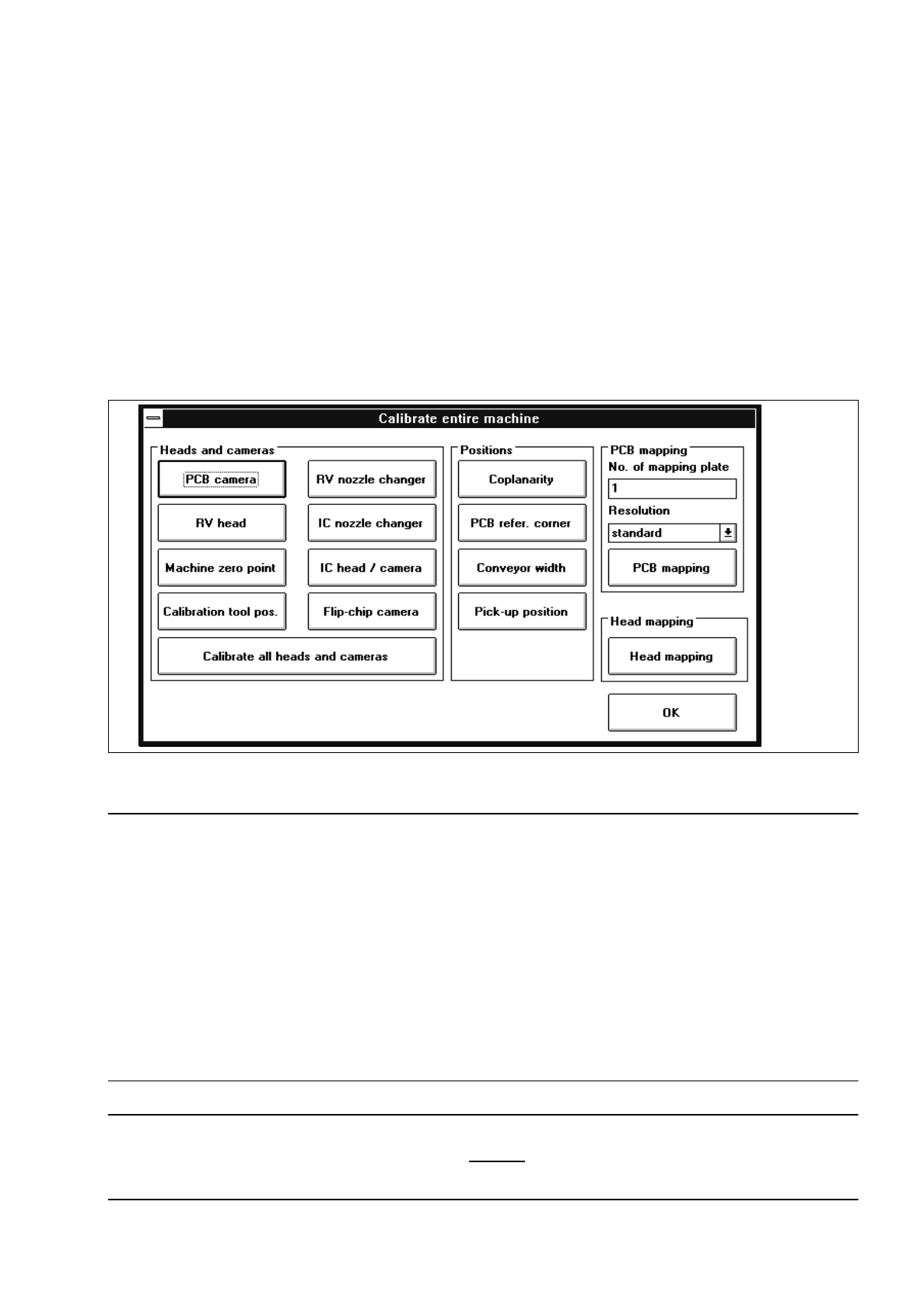
All calibrations described in the following sections can be performed with the aid of the functions contained in
the "Calibrate entire machine" setting box.
In addition, it is also possible to carry out the calibration of the conveyor width (see also chapt. 2, section
2.5.1) and the complete mapping procedure (see also chapt. 4).
●
Carry out the preparatory steps proceeding as described in section 3.1.
●
In the main view click on the Calibrate machine... button.
The setting box below opens.
Fig. 3.2.1 "Calibrate entire machine" Setting Box (Example: "SIPLACE 80F
4
" Machine Type)
NOTE
The sequence in which the calibration of the complete machine has to be performed is governed by the
arrangement of the buttons and whether they can be activated. The operator is automatically guided through
the calibration procedure in that only the function can be activated that is the next permitted function in the
calibration sequence.
If a reference run is required prior to the execution of a particular function, that function cannot be activated
until the appropriate reference run has been performed.
Owing to the fact that prior to the execution of some functions special actions must be taken, the required
work steps are displayed at the appropriate point in dialog boxes. Following the completion of the required
work steps, these dialog boxes have to be closed by clicking on "OK" or "Close" (setting box for Teaching).
NOTE
For measuring the PCB reference corner position, a 100 mm
-wide PCB is to be used as the latter can subse-
quently be also used for the calibration of the conveyor width.

3 Calibration Functions User’s Manual Test Program SITEST
3.2 Complete Calibration of the Machine Software Version 403.xx Edition 12/97
3 - 6
Example: Calibration of the cameras and heads
●
Click on the
PCB camera
button. The calibration of the PCB camera is performed.
All other buttons, except for the "RV head" and "OK" buttons, are inactive.
●
Click on
OK
if you do not wish to perform any other calibrations.
Or:
●
Click on the
RV head
button if you wish to continue with the calibration of the machine.
●
If the complete calibration is to be performed for all individual components contained in the "Heads and
cameras" field, click on the
Calibrate all heads and cameras
button.
The calibration will be carried out in the specified sequence for all heads and cameras available on the
machine.
Example: PCB and head mapping
●
Carry out the preparatory steps proceeding as described in chapt. 4, section 4.1.
●
Place the diskette supplied with the mapping plate into the floppy drive in the control unit.
●
Enter the mapping plate number in the "No. of mapping plate" editing field.
The measured values file associated with the mapping plate is read in after the start of PCB mapping.
●
If you wish to change the resolution that is to be used to determine the data during the mapping run,
click on the "Resolution" field.
●
Select the option for the desired resolution.
●
Click on the
PCB mapping
button. PCB mapping is performed.
●
Following the PCB mapping, click on the
Head mapping
button.
The mapping procedure is started for all heads available on the machine.
When all functions contained in the "Calibrate entire machine" setting box have been performed, the
machine is completely calibrated and a corresponding message box is displayed.
●
Click on
OK
in both the message and setting box.
●
On the menu bar click on
Settings
-->
Save machine data
.
The data is saved to the corresponding files.
User’s Manual Test Program SITEST 3 Calibration Functions
Software Version 403.xx Edition 12/97 3.3 PCB Camera Calibration
3 - 7
3.3 PCB Camera Calibration
●
Carry out the preparatory steps proceeding as described in section 3.1.
●
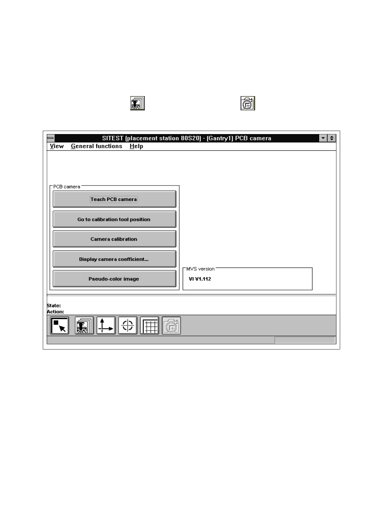
In the "Gantry functions" display (see Fig. 0.3.4) click on the icon to switch to the
"PCB camera functions" display.
Fig. 3.3.1 "PCB camera functions" Display
Overview of the functions:
–
Teach PCB camera to call up the teaching functions
–
Go to calibration tool position to approach the fiducial position (calibration tool)
–
Camera calibration to calibrate the PCB camera
–
Display camera coefficient to display the PCB camera values determined
–
Pseudo-color image to switch the screen display to the pseudo-color image mode
to view the results of any illumination changes
●
Click on the
Camera calibration
button.
The calibration procedure is performed on the PCB camera of the active gantry.