00191021-02.pdf - 第119页
User’s Manual Test Program S ITEST 3 Calibration Functions Software Version 403.xx Edition 12/97 3.7 Calibration of the RV Noz zle Changer 3 - 15 3.7 Cali bratio n of the RV Nozzle Change r NOTE Verify tha t the c alibra…

3 Calibration Functions User’s Manual Test Program SITEST
3.6 Verification of the Calibration Tool Position Software Version 403.xx Edition 12/97
3 - 14
User’s Manual Test Program SITEST 3 Calibration Functions
Software Version 403.xx Edition 12/97 3.7 Calibration of the RV Nozzle Changer
3 - 15
3.7 Calibration of the RV Nozzle Changer
NOTE
Verify that the calibration data for the PCB camera, segment offset
II
(RV-PCB camera offset) and machine
zero point have already been determined.
●
In the main view click on the icon or or to switch the screen display to the "RV head"
display (see Fig. 0.3.5) of the desired RV head.
●
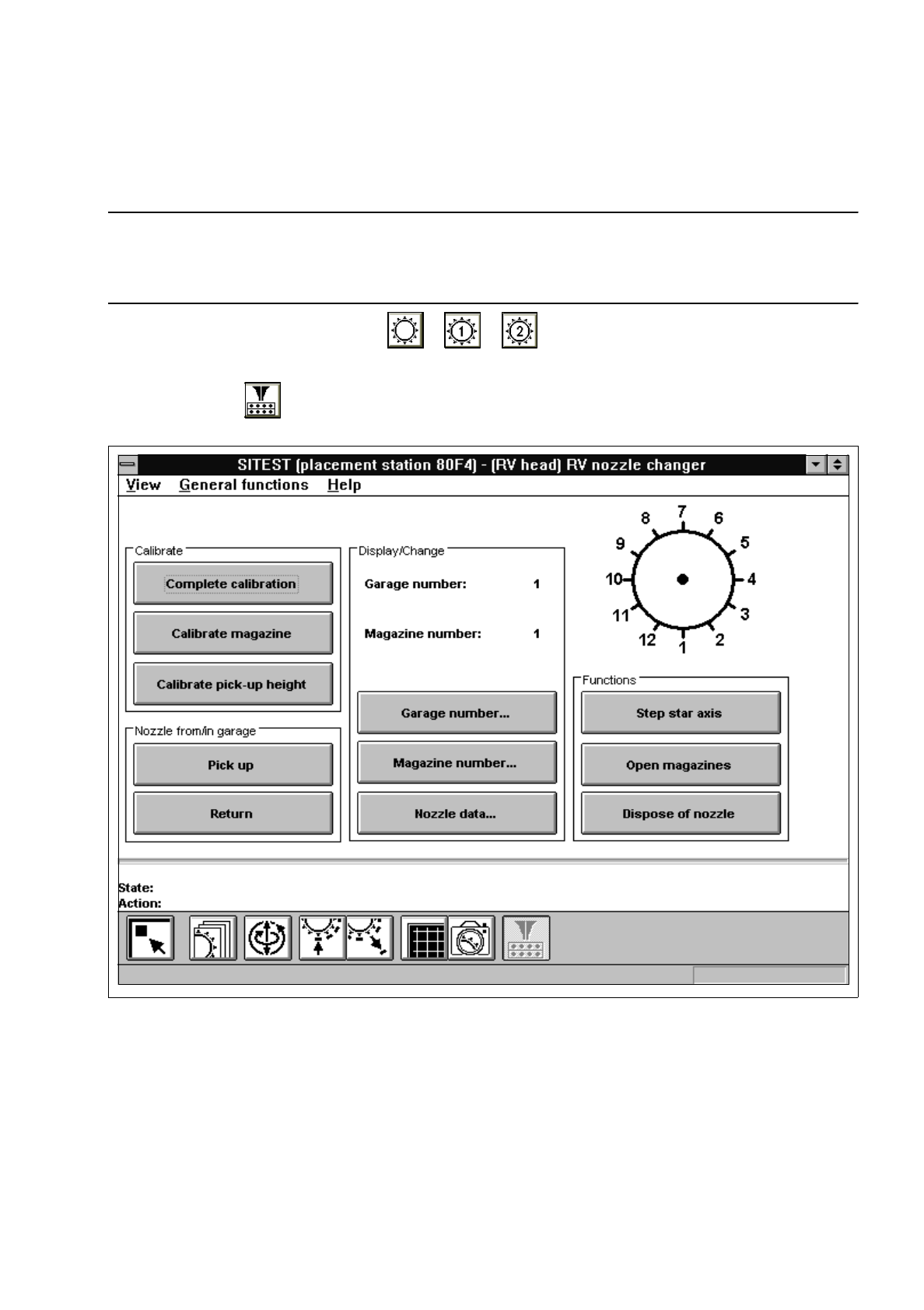
Click on the icon to switch to the "RV nozzle changer" display.
Fig. 3.7.1 "RV nozzle changer" Display
Overview of the functions:
–
Complete calibration to determine the x and y-positions for each magazine
–
Calibrate magazine to determine the x and y-positions for the current magazine
–
Calibrate pick-up height to determine the pick-up height for the current magazine
–
Pick up to remove the nozzle from the selected garage of the current magazine
–
Return to deposit the nozzle in the selected garage of the current magazine
–
Garage number... to open the input box for the garage number
3 Calibration Functions User’s Manual Test Program SITEST
3.7 Calibration of the RV Nozzle Changer Software Version 403.xx Edition 12/97
3 - 16
–
Magazine number... to open the input box for the magazine number
–
Nozzle data... to display the x, y and z-positions determined for the current magazine
–
Step star axis to index the star (for attaching all nozzles to the revolver head)
–
Open magazines to open (move) the locking plate
–
Dispose of nozzle to position the nozzle over the reject box and discard it
NOTE
The "Complete calibration" function is used if the nozzle changer is completely equipped with all 7 maga-
zines. All 12 nozzles must be attached to the 12-nozzle revolver head, or all 6 nozzles to the 6-nozzle
revolver head, respectively.
If the nozzle changer is not
completely equipped with magazines, the x and y-values must be determined
separately for each magazine using the "Calibrate magazine" function.
●
If the nozzle changer is completely equipped with all 7 magazines, click on the
Complete calibration
button. The PCB camera approaches the measuring holes of all magazines in the nozzle changer.
The x and y-values for each magazine compartment are calculated from the positions determined.
●
If the nozzle changer is not completely equipped with magazines, click on the
Magazine number...
button. The input box for the magazine number opens.
●
Enter the desired magazine number and confirm your entry by clicking on
Accept
.
●
Click on the
Calibrate magazine
button.
The PCB camera approaches the measuring hole of the selected magazine. The x and y-values for
each magazine compartment are calculated from the position determined.
●
To determine the pick-up height, enter the numbers of the desired garage and the desired magazine
prior to the calibration procedure using the
Garage number...
and
Magazine number...
functions.
NOTE
For the calibration of the pick-up height, a nozzle must be attached to the segment located at the
bottom and the selected garage must be empty.
●
Subsequently click on the
Calibrate pick-up height
button.
The pick-up height (z-position) determined is displayed in a dialog box after the calibration.
●
Acknowledge the dialog box by clicking on
OK
.
NOTE
For the calibration of the pick-up height, a nozzle must be attached to the segment located at the
bottom and the selected garage must be empty.
The z-position of the reject box will be calculated on the basis of the pick-up height determined for the
last magazine.