00191021-02.pdf - 第157页
User’s Manual Test Program S ITEST 4 Mapping Software Version 403.xx Edition 07/97 4.2 PCB Mapping 4 - 5 4.2 P CB Ma ppin g NOTE Verify tha t the cali bration data for the RV c amera, PC B camera, seg ment off set II (R …

4 Mapping User’s Manual Test Program SITEST
4.1 Preparatory Steps for the Mapping Operation Software Version 403.xx Edition 07/97
4 - 4
User’s Manual Test Program SITEST 4 Mapping
Software Version 403.xx Edition 07/97 4.2 PCB Mapping
4 - 5
4.2 PCB Mapping
NOTE
Verify that the calibration data for the RV camera, PCB camera, segment offset
II
(RV-PCB camera offset)
and the MA zero point have already been determined. Furthermore, prior to the performance of the mapping,
the width adjustment must have been calibrated.
●
In the main view click on the icon (for gantry 1 of SIPLACE 80S-20) or the icon (for the gantry of
SIPLACE 80F
4
)
to switch the screen display to the "Gantry" display (see Fig. 0.3.4).
●
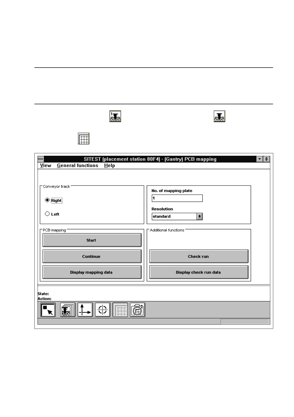
Click on the icon to switch to the "PCB mapping" display.
Fig. 4.2.1 "PCB mapping" Display

4 Mapping User’s Manual Test Program SITEST
4.2 PCB Mapping Software Version 403.xx Edition 07/97
4 - 6
The following functions are available in the "PCB mapping" display:
–
Right to select the right conveyor track
–
Left to select the left conveyor track of a dual conveyor
–
Start to start the mapping run
–
Continue to continue mapping
–
Display mapping data to display the mapping data determined
–
PCB mapping both gantries to perform the mapping run for both gantries of the SIPLACE
80S-20 (switching from one gantry to the other is carried out auto-
matically. The mapping run is first carried out for gantry 1, then for
gantry 2).
–
Check run to approach the mapping positions for checking purposes (one
position per row)
–
Display check run data to display the setpoint positions calculated during the mapping
check and the deviations measured
(taking into account the correction values from the measured
values file, the rotational offset angle, the gantry offset, etc.)
●
If a dual conveyor is installed, activate the appropriate radio button
Right
or
Left
in the "Conveyor
track" field, depending on which conveyor track you wish to perform the mapping.
●
If you wish to change the resolution that is used to determine the data during the mapping run, click on
the "Resolution" field.
The following options are available:
–
standard 13 x 11 measuring points will be determined with a fiducial spacing of 40 mm
–
high 25 x 21 measuring points will be determined with a fiducial spacing of 20 mm
●
Select the option for the desired resolution.
NOTE
Each mapping plate is delivered with a diskette containing a measured values file. This file contains the
values of the deviation of the measuring points from their setpoint positions. These values are required for
PCB mapping for correction purposes. Only after the plate number (see below) has been entered can the
PCB mapping run be started. The measured values file is read in from diskette upon the start of the
mapping run.
●
Place the diskette supplied with the mapping plate into the floppy drive of the control unit.
●
Enter the number of the mapping plate in the "No. of mapping plate" editing field.