00191021-02.pdf - 第128页
3 Calibration Functions User’s Manual Test Program S ITEST 3.10 Calibration of t he Flip-Chip Camera (SIPLACE 80F4) Software Version 403.xx Edition 12/97 3 - 24 ● Click on t he Calibr. flip-chip cam era button. The ca li…
User’s Manual Test Program SITEST 3 Calibration Functions
Software Version 403.xx Edition 12/97 3.10 Calibration of the Flip-Chip Camera (SIPLACE 80F4)
3 - 23
3.10 Calibration of the Flip-Chip Camera (SIPLACE 80F
4
)
●
Carry out the preparatory steps proceeding as described in section 3.1.
●
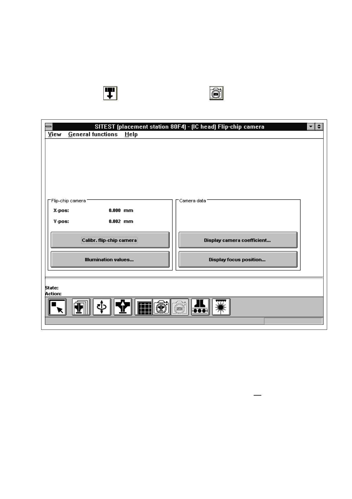
In the "IC head" display (see Fig. 0.3.6) click on the icon to switch to the "Flip-chip camera"
display.
Fig. 3.10.1 "Flip-chip camera" Display
Overview of the functions:
–
Calibr. flip-chip camera to calibrate the Flip-Chip camera
–
Illumination values... to display the illumination values
(Normally, the illumination values do not need to be changed.
Changing the values in a non-expert manner will lead to incorrect
calibration results).
–
Display camera coefficient... to display the Flip-Chip camera values determined
–
Display focus position... to display the camera position and focus height determined

3 Calibration Functions User’s Manual Test Program SITEST
3.10 Calibration of the Flip-Chip Camera (SIPLACE 80F4) Software Version 403.xx Edition 12/97
3 - 24
●
Click on the
Calibr. flip-chip camera
button.
The calibration of the Flip-Chip camera is now performed.
●
If you wish to view the values determined after the completion of the calibration procedure, click on the
Display camera coefficient...
button.
●
If you wish to view the values for the camera position and focus height, click on the
Display focus
position...
button.
NOTE
The x and y-values of the current camera position are also displayed in the "Camera position" field.
●
Click on the icon to return to the main view.
User’s Manual Test Program SITEST 3 Calibration Functions
Software Version 403.xx Edition 12/97 3.11 Calibration of the Coplanarity Laser Module (SIPLACE 80F4)
3 - 25
3.11 Calibration of the Coplanarity Laser Module
(SIPLACE 80F
4
)
NOTE
Prior to the calibration of the coplanarity module, all calibration operations described earlier in this chapter
must have been performed.
●
Carry out the preparatory steps proceeding as described in section 3.1. However, place the coplanarity
calibration tool into the "calibration tool pocket" in lieu of the "normal" calibration tool (see Fig. 3.12.1).
●
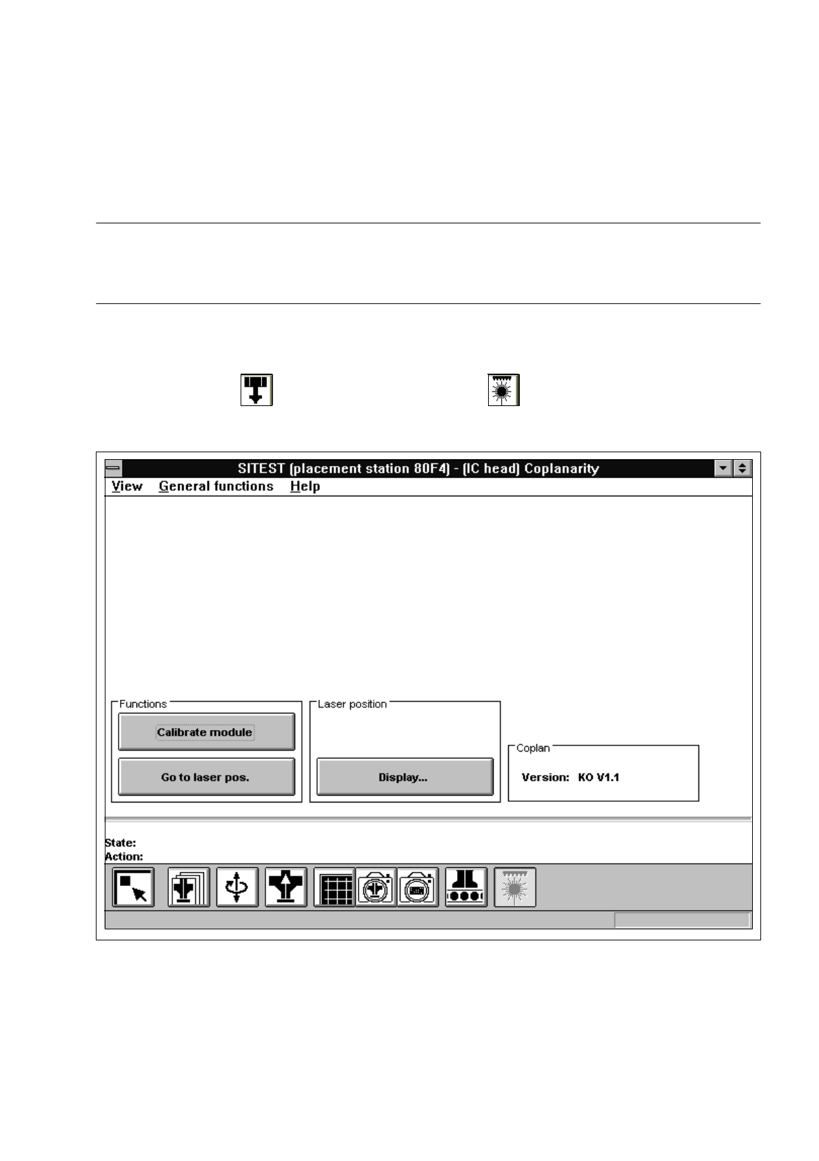
In the "IC head" display (see Fig. 0.3.6) click on the icon to switch to the "Coplanarity
functions" display.
Fig. 3.11.1 "Coplanarity functions" Display
Overview of the functions:
–
Calibrate module to calibrate the coplanarity module
–
Go to laser pos. to approach the laser with the PCB camera to check the laser position
–
Display... to display the laser position and focus height determined