00191021-02.pdf - 第150页
4 Mapping User’s Manual Test Program S ITEST 4.3 RV Mapping Software Version 403.xx Edition 07/ 97 4 - 12 NOTE RV mapping can al so be perfo rmed u sing the Calibrate ma chine... --> Head mapping func tion (se e chap …

User’s Manual Test Program SITEST 4 Mapping
Software Version 403.xx Edition 07/97 4.3 RV Mapping
4 - 11
4.3.1 Mapping Run for Both Gantries (SIPLACE 80S-20)
●
Click on the
Start
button in the
"
RV mapping both gantries
"
field.
The mapping run is performed for gantry 1. After the mapping run, gantry 1 is automatically moved to
the park position and subsequently the mapping run for gantry 2 is performed.
After the mapping run has been completed without any errors, the data thus determined is automatically
saved.
●
If a dual conveyor is installed, activate the radio button for the conveyor track for which mapping has
not yet been performed.
●
Click on the
Start
button in the
"
RV mapping both gantries
"
.
The mapping run is performed for both gantries on the selected conveyor track.
After the mapping run has been completed without any errors, the data thus determined is automatically
saved.
●
Click on the icon to return to the main view.
4.3.1.1 Mapping Run for the Second Gantry
●
Click on the
Start
button in the "RV mapping of selected gantry" field.
The active gantry now performs the mapping run. After the mapping run has been completed without
any errors, the data thus determined is automatically saved.
●
If a dual conveyor is installed, activate the radio button for the conveyor track for which mapping has
not yet been performed.
●
Click again on the
Start
button in the
"
RV mapping of selected gantry
"
field.
The active gantry performs the mapping run on the selected conveyor track. After the mapping run has
been completed without any errors, the data thus determined is automatically saved.
●
Click on the icon to return to the main view.
●
In the main view "SIPLACE 80S-20" click on the icon to switch to the "RV head 2" display.
●
Click on the icon to switch to the "RV mapping" display.
●
Click on the
Start
button in the
"
RV mapping of selected gantry
"
field.
Gantry 2 now performs the mapping run.
After the mapping run has been completed without any errors, the data thus determined is automatically
saved.
●
If a dual conveyor is installed, activate the radio button for the conveyor track for which mapping has
not yet been performed.
●
Click again on the
Start
button in the
"
RV mapping of selected gantry
"
field.
●
Gantry 2 performs the mapping run on the selected conveyor track.
After the mapping run has been completed without any errors, the data thus determined is automatically
saved.
●
Click on the icon to return to the main view.

4 Mapping User’s Manual Test Program SITEST
4.3 RV Mapping Software Version 403.xx Edition 07/97
4 - 12
NOTE
RV mapping can also be performed using the
Calibrate machine...
-->
Head mapping
function (see chapt. 3,
section 3.2). On SIPLACE 80S-20 machine types, this function is used to perform automatically the mapping
procedure, first for gantry 1 and then for gantry 2.
If a dual conveyor is installed on the machine, mapping is performed first on the right and then on the left
conveyor track.
User’s Manual Test Program SITEST 4 Mapping
Software Version 403.xx Edition 07/97 4.4 IC Mapping
4 - 13
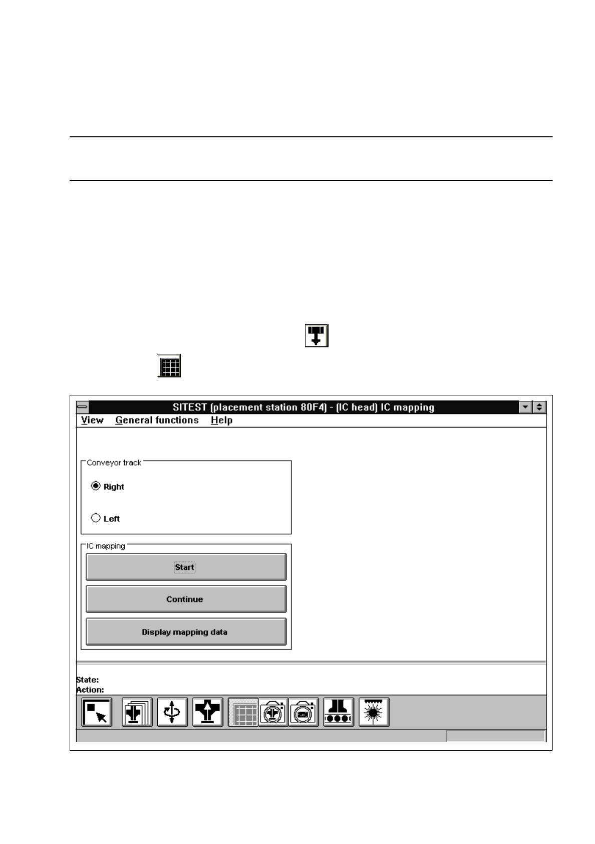
4.4 IC Mapping
NOTE
Prior to the performance of IC mapping make sure that PCB mapping has already been carried out.
●
Carry out the preparatory steps as described in section 4.1.
Additional prerequisites are:
–
Segment offset
II
(RV-PCB camera offset) must already have been determined.
–
The calibration tool must be in the calibration tool pocket.
–
The calibration tool position must already have been determined.
–
The IC camera must have been completely calibrated.
–
On the IC head, a type 416 nozzle must be attached.
●
In the main view "SIPLACE 80F
4
" click on the icon to switch to the "IC head" display.
●
Click on the icon to switch to the "IC mapping" display.
Fig. 4.4.1 "IC mapping" Display