00193463-01.pdf - 第114页
3 What to do when .. . User Manual SIPLACE S-25 HM 3.6 Preliminary set-up of the placement station Software Version SR.503.xx 04/2002 US Edition 114 3.6 Preliminary se t-up of the placement st ation Carry out th e foll o…
User Manual SIPLACE S-25 HM 3 What to do when ...
Software Version SR.503.xx 04/2002 US Edition 3.5 When you, as an operator, carry out a walk-through inspection
113
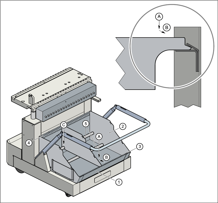
Fig. 3.5 - 2 Dividing plates in the tape container
(1) Tape container
(2) Dividing plate
(3) Guide rail for the dividing plates on the front of the container
(4) Guide rail for the dividing plates on the back of the container
(5) Supporting rod for the dividing plates
Steps
A Insert the dividing plate with the nose under the guide rail on the front of the container.
B Push the dividing plate in direction (B).
C Engage the dividing plate on the supporting rod (5).
3 What to do when ... User Manual SIPLACE S-25 HM
3.6 Preliminary set-up of the placement station Software Version SR.503.xx 04/2002 US Edition
114
3.6 Preliminary set-up of the placement station
Carry out the following steps to complete the preliminary set-up of the placement station.
Æ Remove the tapes from the feeder modules and vacuum the surfaces of the modules and the
area around the tape guide clean with the vacuum cleaner.
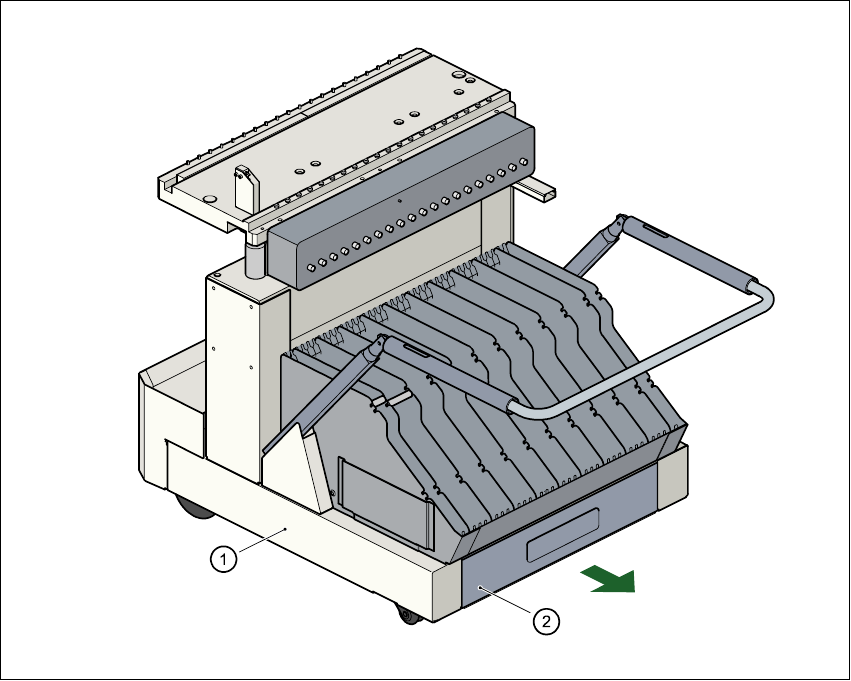
Æ Remove the cover foil from the tape waste containers (item 2).
Fig. 3.6 - 1 Emptying the tape waste container
(1) Component changeover table, mobile (2) Waste tape container, extendible
Æ Clean the supporting surfaces of the feeder modules with a cloth moistened with alcohol.
Æ Apply a small amount of WD40 corrosion protection to the supporting surfaces with a lint-free
cloth.
Æ Use a vacuum cleaner or use a brush with short bristles to remove loose components from the
component tables.

User Manual SIPLACE S-25 HM 3 What to do when ...
Software Version SR.503.xx 04/2002 US Edition 3.6 Preliminary set-up of the placement station
115
CAUTION
Avoid removing components from the magnetic rail of the component table with your fingers
or you may injure yourself with tiny splinters of metal. 3
NOTE
The compressed air distributor rail on the component tables is used to connect the bulk case
feeder modules. This rail runs parallel to the PCB transport and has nozzles with the open-
ings on the top. Make sure that the nozzles do not get dirty or come into contact with oil or
grease. Grease, oil and dirt can cause malfunctions in the feeder module or may cause the
components in the feeder module to become unusable! 3
Æ Cover the nozzles on the distributor rail with electrical tape, for example.
Æ Check the surface of the magnetic rail for irregularities or damage and smoothen with an oil-
stone when necessary.
Æ Clean the magnetic rail with a cloth moistened with alcohol.
Æ Apply a small amount of WD40 corrosion protection to the magnetic rail with a lint-free cloth.
Æ Clean the supporting surfaces of the component tables with a cloth moistened with alcohol,
and then apply a small amount of WD40 corrosion protection with a lint-free cloth.
Æ Clean the tape container with a vacuum cleaner.
Æ Make sure that the feeder modules are divided up correctly.
Æ Are all the plugs of the feeder module plugged in to the correct location?
Æ Make sure that the spacing in the tape transport of the feeder is correct.
Æ Shorten the used tape on the front of the feeder module to a length of 3 cm.
Æ Check to see if the dividing plates in the tape container are inserted correctly (see Fig. 3.5 - 2).
Æ Check the diameter of the component tape reels and insert a shaft for large reels.
Æ Splice short tape ends together.
The personnel maintaining the preliminary set-up area is to have access to the same equipment
as the machine operators. You will find a list of such equipment in section 3.12.
NOTE
If the equipment is defective, then the machine operator is to inform the personnel in the prelimi-
nary set-up area verbally or in writing.