00193463-01.pdf - 第173页
User Manual SIPLAC E S-25 HM 5 Station extensions Software Vers ion SR.503.xx 04/2002 US Edition 5.3 Dual conv eyor 173 5.3.9 T e chnica l data – dual conveyor system 5 5 5.3.10 Mainte nance The indivi dual c onveyor bel…

5 Station extensions User Manual SIPLACE S-25 HM
5.3 Dual conveyor Software Version SR.503.xx 04/2002 US Edition
172
5.3.6 Synchronous conveyor mode
5.3.6.1 Description
In synchronous mode, two PCBs of the same size are moved into the placement position
together. These PCBs must be processed as a common cluster.
This enables the topside and underside of a PCB to be processed on the same line. As a result,
it takes less time to transport the PCBs since two PCBs are always moved at the same time.
5.3.6.2 Function
PCBs on conveyor tracks 1 and 2 are moved synchronously onto the conveyor sections (i.e. the
conveyors are controlled synchronously, but independently of one another). The components to
be placed on conveyor tracks 1 and 2 must be organized into a cluster via two subpanels. (See
the user manual for the line computer).
If only one conveyor track (or center conveyor) is full when the placement sequence starts, the
subpanel on this section will be identified as “not for placement”.
5.3.6.3 Restrictions
If the dual conveyor is operated in synchronous mode, the ‘PCB whispering down the line’ option
is deactivated. PCB barcode operation is not supported in this mode. The ‘Global ink spot’ option
cannot be used.
5.3.7 Controlling the dual conveyor using the Single Functions menu
The online help contains information on controlling the dual conveyor and on the Single Functions
menu.
5.3.8 Automatic width adjustment on the dual conveyor
The desired conveyor width relates to both conveyors. When the command is received, the con-
veyors are set to the desired width one after another.
PLEASE NOTE 5
Automatic width adjustment is deactivated if “synchronous transport” is selected.

User Manual SIPLACE S-25 HM 5 Station extensions
Software Version SR.503.xx 04/2002 US Edition 5.3 Dual conveyor
173
5.3.9 Technical data – dual conveyor system
5
5
5.3.10 Maintenance
The individual conveyor belts and the additional lifting table require the same maintenance as the
standard conveyor. Each conveyor belt must be maintained as described in the maintenance in-
structions. 5
PCB format
(length x width)
50 mm x 50 mm to 508 mm x 216 mm
(2" x 2" to 20" x 8.5")
Long-board option: length up to 610 mm (24")
PCB thickness 0.5mm to 4.5mm
Max. PCB warpage On top: 4.5mm - PCB thickness
On bottom: 0.5mm + PCB thickness
Clearance on PCB underside 25mm (standard), 40mm (option)
PCB transport height 830mm ± 15mm (standard)
900mm ± 15mm (option)
930mm ± 15mm (option)
950mm ± 15mm (SMEMA optional)
Stationary conveyor side Right (standard), left (optional)
Type of interface Siemens (standard)
SMEMA (option)
Component-free handling edge 3mm
PCB changeover time 2.5 s
Type of transportation synchronous or asynchronous
Components on each conveyor synchronous: different, asynchronous: same
PCB width on each conveyor synchronous: different, asynchronous: same
Ink spot recognition synchronous: not possible, asynchronous: possible
Automatic width adjustment synchronous: not possible, asynchronous: possible
5 Station extensions User Manual SIPLACE S-25 HM
5.4 PCB barcode Software Version SR.503.xx 04/2002 US Edition
174
5.4 PCB barcode
5.4.1 Overview
The PCB barcode reader is used to automatically record and decode barcodes on PCBs. The
PCB barcode reader sends the read data via its serial interface to the machine controller for fur-
ther processing. 5
The PCB barcode readers are installed on the input side of the placement machine, above and
below the PCB conveyor, so that barcode labels on the topside and underside of the PCBs can
be read.
One or two PCB barcode readers may be retrofitted in order to read the topside and underside of
the PCB on the transport track. 5
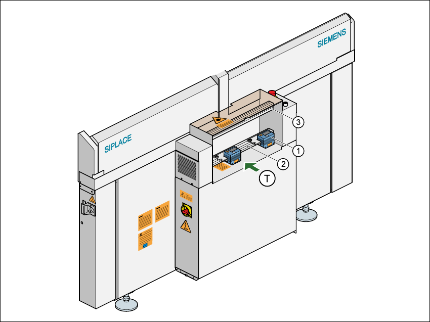
Fig. 5.4 - 1 Position of the modules on the input side of the placement machine
(1) PCB barcode reading head
(2) Profiled rail for ‘underside’ PCB barcode reader
(3) Profiled rail for ‘topside’ PCB barcode reader
(T) Direction of PCB transport 5