00193463-01.pdf - 第205页
User Manual SIPLAC E S-25 HM 5 Station extensions Software Version SR.503.xx 04/2002 US Edition 5.12 DCA vision module on the 6-segm ent Collect&Place head 205 5.12 DC A visi on modu le on th e 6-segm ent Collect&…
5 Station extensions User Manual SIPLACE S-25 HM
5.11 DCA vision module on the 12-segment Collect&Place head Software Version SR.503.xx 04/2002 US Edition
204
5.11.3 Technical data – DCA vision module
5
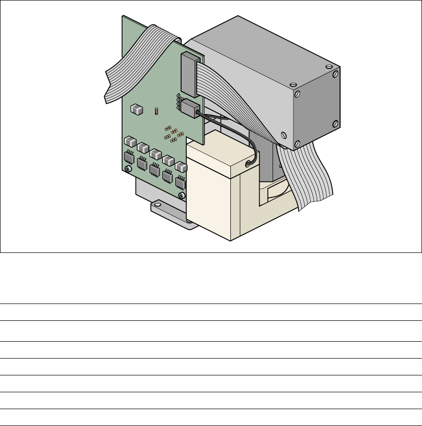
Fig. 5.11 - 2 Component vision module (DCA camera)
5
5
5
Component dimensions 0.6 mm x 0.3 mm to 13 mm x 13 mm
Component range 0201 up to 13 mm x 13 mm, flip-chip, bare die
Min. lead pitch 0.4 mm
Minimum bump pitch 0.2 mm
Min. ball/bump diameter 0.11 mm
Field of view 15.7 mm x 15.7 mm
Illumination method Front lighting (4 levels programmable as required)
User Manual SIPLACE S-25 HM 5 Station extensions
Software Version SR.503.xx 04/2002 US Edition 5.12 DCA vision module on the 6-segment Collect&Place head
205
5.12 DCA vision module on the 6-segment
Collect&Place head
5
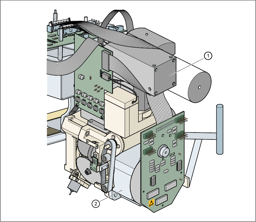
Fig. 5.12 - 1 DCA vision module on the 6-segment Collect&Place head
5
(1) DCA vision module
(2) 6-segment Collect&Place head

5 Station extensions User Manual SIPLACE S-25 HM
5.12 DCA vision module on the 6-segment Collect&Place head Software Version SR.503.xx 04/2002 US Edition
206
5.12.1 Description of the 6-segment Collect&Place head with
DCA vision module
With the DCA vision module, the 6-segment Collect&Place head is able to optically center and
place components of the order of magnitude of 0.6 mm x 0.3 mm to 13 mm x 13 mm. The DCA
package optimizes the speed and accuracy when placing high-speed flip chips and bare die
components.
5.12.2 Technical data for the 6-segment Collect&Place head with
DCA vision module
5
PLEASE NOTE 5
The technical data for the DCA vision module is given in section 5.11.3 on page 204. 5
5
Component range 0201 to 13 mm x 13 mm
Component specification
Max. height
Min. lead pitch
Min. bump pitch
Min. ball/bump diameter
Min. dimensions
Max. dimensions
Max. weight
8.5 mm
0.4 mm
0.2 mm
0.11 mm
0.6 mm x 0.3 mm
13 mm x 13 mm
5 g
Travel of the Z axis max. 16 mm
Programmable placement force 2.4 to 5.0 N
Nozzle types 8xx, 9xx
Max. placement rate 8.500 components/hour
Angular accuracy ± 0.4° / 4
σ
Placement accuracy of the DCA vision module ± 70 µm / 4 σ