00193463-01.pdf - 第212页
5 Station extensions User Manual SIPLACE S-25 H M 5.14 SIPLACE productivity lift S oftware Version SR.503.xx 04/2002 US Edition 212 5.14.3 Advant a ges of the productivity lift The pro ductivity lift can raise the prod u…
User Manual SIPLACE S-25 HM 5 Station extensions
Software Version SR.503.xx 04/2002 US Edition 5.14 SIPLACE productivity lift
211
5.14.2 Implementing parallel placement
Lines with machines arranged in parallel take up a lot more space, so the parallel placement con-
cept was implemented with an underfloor conveyor and horizontal / vertical lift (HV shuttle). The
machines are still arranged in series, but the lift units and underfloor conveyors allow the line to
be operated in parallel. In this way, SIPLACE lines remain almost as compact as before.
Underfloor conveyor
Two conveyor belts carry empty or placed PCBs underneath the machines (see Fig. 5.14 - 1).
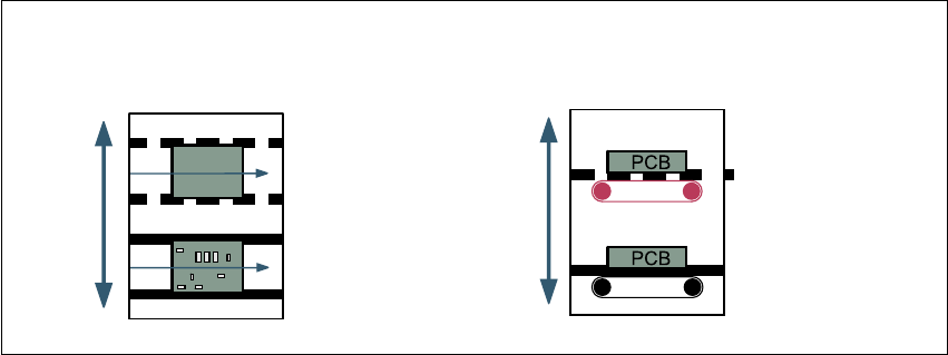
Horizontal/vertical lift (horizontal/vertical shuttle)
There is an HV shuttle at the start of a line, between the machines and at the end of the line. It
carries the PCBs between the underfloor and processing levels, and between the two tracks on
the underfloor conveyors.
5
Fig. 5.14 - 2 Horizontal / vertical shuttle (HV shuttle), conveyor track change and lift function
Horizontal conveyor
HV shuttle
Lift function
Vertical conveyor
Unplaced
Placed
Standard
conveyor level
Underfloor
conveyor level
HV shuttle
Conveyor track change
5 Station extensions User Manual SIPLACE S-25 HM
5.14 SIPLACE productivity lift Software Version SR.503.xx 04/2002 US Edition
212
5.14.3 Advantages of the productivity lift
The productivity lift can raise the productivity of a line overall because it increases the placement
rates of the machines on the line.
5
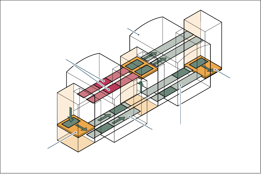
Fig. 5.14 - 3 Productivity lift – avoiding stoppages
If lines are connected in parallel, individual machines may fail without bringing the entire line to a
standstill. It is also possible access individual machines while the rest of the line continues plac-
ing without interruption.
This could be for
– process-related investigations or test operation
– programming PCB fiducials, package forms or test placements
– maintenance or repairs
– operating errors, such as not splicing tapes on in good time or missing components.
Another advantage is that the line can be reconfigured as required using the software, without
having to reset the machines.
PCB conveyor section being
placed
Placement machine
Horizontal
and vertical lift
Underfloor conveyor
Track change

User Manual SIPLACE S-25 HM 5 Station extensions
Software Version SR.503.xx 04/2002 US Edition 5.14 SIPLACE productivity lift
213
5.14.4 Technical data
5
5
Supply voltage 230/400 V~, 110/230 V~, ± 10%, 50/60 Hz
Total connected load 0.5 kVA
Total power 0.5 kW (2 A connected load)
Fuses 6.3 A
Power failure Up to 20 msec
Compressed air connection Min. 5.0 bar, 10 NL/min
Length of the conveyor section 1595 mm
Length of the HV shuttle 540 mm
Width of the HV shuttle 1045 mm
Height of the HV shuttle 1200 mm (for conveyor height of 930 mm)
Weight of the HV shuttle 212 kg
Weight of the underfloor section 90 kg
Permissible load per unit area on foundation Min. 0.2 t/m²
Room temperature Between 15 °C and 35 °C
Atmospheric humidity 30 - 70%, but no higher than 45% on average
in order to prevent any possibility of conden-
sation on the machine.
Max. noise generated 62 dBA
PCB conveyor height 930 ± 30 mm
PCB dimensions
Width
Length
Thickness
50 mm - 216 mm (2" – 8.5")
50 mm -460 mm (2" -18")
0.5 mm - 4.5 mm