00193463-01.pdf - 第174页
5 Station extensions User Manual SIPLACE S-25 H M 5.4 PCB barcode Software Version SR.503.xx 04/2002 US Edition 174 5.4 PCB barcode 5.4.1 Overvie w The PCB barcode reader is used to autom atica lly recor d and decode ba …

User Manual SIPLACE S-25 HM 5 Station extensions
Software Version SR.503.xx 04/2002 US Edition 5.3 Dual conveyor
173
5.3.9 Technical data – dual conveyor system
5
5
5.3.10 Maintenance
The individual conveyor belts and the additional lifting table require the same maintenance as the
standard conveyor. Each conveyor belt must be maintained as described in the maintenance in-
structions. 5
PCB format
(length x width)
50 mm x 50 mm to 508 mm x 216 mm
(2" x 2" to 20" x 8.5")
Long-board option: length up to 610 mm (24")
PCB thickness 0.5mm to 4.5mm
Max. PCB warpage On top: 4.5mm - PCB thickness
On bottom: 0.5mm + PCB thickness
Clearance on PCB underside 25mm (standard), 40mm (option)
PCB transport height 830mm ± 15mm (standard)
900mm ± 15mm (option)
930mm ± 15mm (option)
950mm ± 15mm (SMEMA optional)
Stationary conveyor side Right (standard), left (optional)
Type of interface Siemens (standard)
SMEMA (option)
Component-free handling edge 3mm
PCB changeover time 2.5 s
Type of transportation synchronous or asynchronous
Components on each conveyor synchronous: different, asynchronous: same
PCB width on each conveyor synchronous: different, asynchronous: same
Ink spot recognition synchronous: not possible, asynchronous: possible
Automatic width adjustment synchronous: not possible, asynchronous: possible
5 Station extensions User Manual SIPLACE S-25 HM
5.4 PCB barcode Software Version SR.503.xx 04/2002 US Edition
174
5.4 PCB barcode
5.4.1 Overview
The PCB barcode reader is used to automatically record and decode barcodes on PCBs. The
PCB barcode reader sends the read data via its serial interface to the machine controller for fur-
ther processing. 5
The PCB barcode readers are installed on the input side of the placement machine, above and
below the PCB conveyor, so that barcode labels on the topside and underside of the PCBs can
be read.
One or two PCB barcode readers may be retrofitted in order to read the topside and underside of
the PCB on the transport track. 5
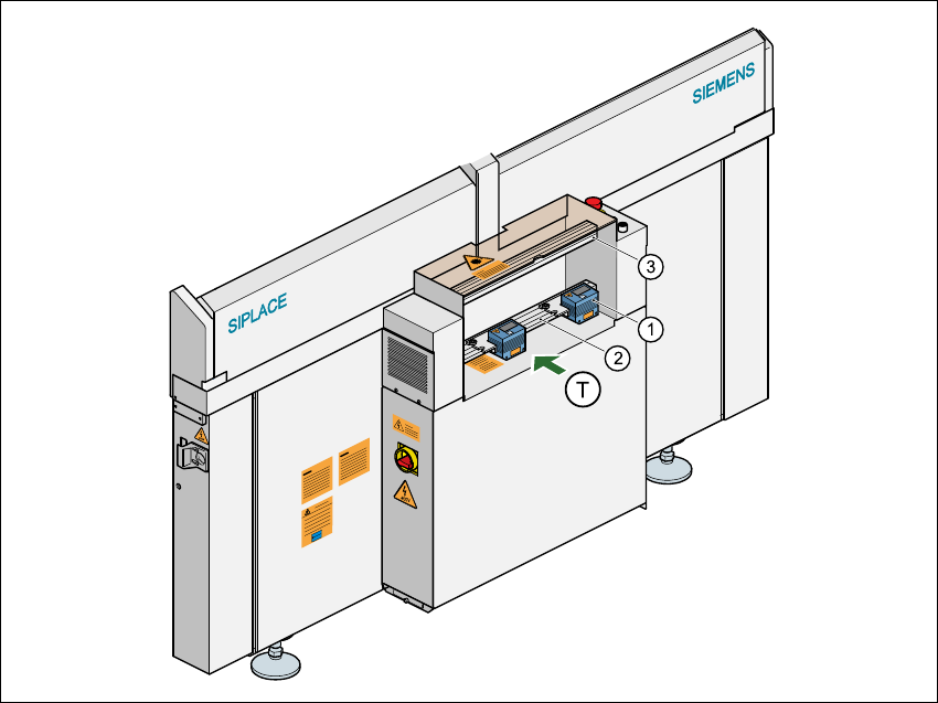
Fig. 5.4 - 1 Position of the modules on the input side of the placement machine
(1) PCB barcode reading head
(2) Profiled rail for ‘underside’ PCB barcode reader
(3) Profiled rail for ‘topside’ PCB barcode reader
(T) Direction of PCB transport 5
User Manual SIPLACE S-25 HM 5 Station extensions
Software Version SR.503.xx 04/2002 US Edition 5.4 PCB barcode
175
The PCB barcode readers are fixed to the top and bottom profiled rail using retainers. These can
be positioned as required on the profiled rails, and aligned with respect to the barcode labels. De-
pending on the position of the barcode strips, the barcode reader can be attached in a few simple
steps so that the strips can be read parallel to or across the PCB transport direction. 5
5.4.2 Laser safety instructions
Laser radiation 5
The radiation from the laser diode (infrared or IR
light) of the PCB barcode reader is harmful to the
human eye, 5
Æso you should never look into the laser beam.
ÆNever direct the PCB barcode reader into other
people’s eyes.
ÆWhen installing the barcode reader, make sure
that the laser beam cannot be not reflected during
use.
If you open the housing during use, the scanning cy-
cle will continue, and the laser diode will continue to
switch on. 5
The laser beam output at the barcode template win-
dow does not exceed 1.0 mW. The PCB barcode
reader thus conforms to protection class 2. 5
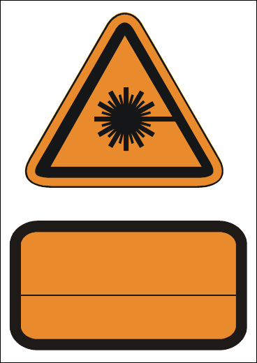
Fig. 5.4 - 2 Laser safety instructions for the
PCB barcode reader
5.4.3 Functional description
5.4.3.1 PCB barcode reader for the single conveyor
The SIPLACE PCB barcode reader supports the flexible manufacture of SMD products, and in-
creases placement reliability. It recognizes all the code types conventionally used in industrial ap-
plications. 5
The laser scanner reads the barcode label on the topside or underside of each incoming PCB as
they are transported onto the input conveyor. The barcode data enables the line computer to au-
tomatically select the correct barcode allocation list from the previously created barcode assign-
ment list, and sends it to the station. If a barcode filter was defined, only the data that is identified
as relevant will be compared in the barcode. This procedure is carried out time neutrally during
placement of the PCB already in the machine. If several PCBs with the same barcode enter in
LASERSTRAHLUNG
NICHT IN DEN STRAHL BLICKEN
LASERKLASSE 2
EN 60825 1991
Max. Ausgangsleistung:1,0 mW
Wellenlänge: 670 nm