00193463-01.pdf - 第120页
3 What to do when .. . User Manual SIPLACE S-25 HM 3.8 Component table, mobile Software Version SR.503.xx 04/2002 US Edition 120 3.8.3 Docking the component t able W ARNING 3 Check tha t the plac ement he ad is outside t…

User Manual SIPLACE S-25 HM 3 What to do when ...
Software Version SR.503.xx 04/2002 US Edition 3.8 Component table, mobile
119
Key to Fig. 3.8 - 2
(1) Communication interface connector
(2) Power supply connector for the component table
(3) Compressed air connection
(4) Component table bed
(5) Button for raising and lowering the component table bed
(6) Actuating tube
(7) Fold-down bracket
(8) Holes for the centering pins
(9) Centering pins
(10) Contact surfaces for the slide rails of the component table
(11) Horizontal tensioners
(12) Movable cover that ensures that the power supply and control cables are plugged in and
removed in the correct order.
Æ Click on the STOP PROCESSING PCB icon in the MAIN VIEW menu.
Æ The PCB in progress will be completed. The icons of the SINGLE FUNCTIONS menu will then
be activated.
Æ Click on the desired SINGLE FUNCTIONS GANTRY X icon (gantry 1 or 2).
Æ Click on the GANTRY FUNCTIONS icon.
Æ From this menu, click on the GO TO SET-UP POSITION button.
Æ The selected placement head will move across the PCB transport to prevent it being damaged
when the component table is changed.
Æ Open protective cover of the selected gantry.
Æ Open the side screens.
Æ Open the horizontal tensioners (item 11).
Æ Pull the two actuating tubes (item 6) towards you at the same time and lift up the bracket (item
7) to lock the raised component table bed in its top end position.
Æ Hold down the button (item 5) for raising the component table bed (item 4) until the component
table bed reaches its top end position.
Æ Unplug the component table power cable (item 2).
Æ Move the cover (item 12) sideways until you can unplug the control cable (item 1).
Æ Unplug the component table control cable (item 1).
Æ Disconnect the compressed air supply (item 3).
Æ Remove the component table.
3 What to do when ... User Manual SIPLACE S-25 HM
3.8 Component table, mobile Software Version SR.503.xx 04/2002 US Edition
120
3.8.3 Docking the component table
WARNING 3
Check that the placement head is outside the range of the component table. 3
CAUTION 3
When docking the component table, ensure that the table bed is in its top end position and the
bracket (item 7) is folded up. 3
Æ Cut off the empty tapes for the feeder modules.
Æ Make sure that the contact surface (item 10) for the component table bed is clean.
Æ CAREFULLY push the component table into the placement system.
Æ Connect the compressed air supply (item 3).
Æ Plug in the control cable (item 1).
Æ Move the cover (item 12) over the control cable plug to expose the power supply socket.
Æ Plug in the power cable (item 2) for the component table.
Æ Pull the two actuating tubes (item 6) towards you at the same time and then lower the bracket
(item 7) in order to be able to lower the component table bed.
Æ Check that the centring holes in the component table bed lie precisely over the centering pins
of the placement system.
Æ Hold down the button (item 5) until the component table bed reaches its top end position.
Æ Release the button and the component table bed will descend.
Æ Ensure that the centring pins engage in the centring holes in the component table bed and that
the component table bed is fully lowered.
Æ Fold up the bracket (item 7) of the component table.
Æ Lock the two horizontal tensioners (item 11).
Æ Close the side screens and protective cover.
Æ Press the Start button to start the placement system.
User Manual SIPLACE S-25 HM 3 What to do when ...
Software Version SR.503.xx 04/2002 US Edition 3.9 How to avoid track errors
121
3.9 How to avoid track errors
3.9.1 General information
Æ Make sure that the areas around the feeder modules are clean and that there are no loose
components in the feeder area or under the feeder modules.
Æ Ensure that the supporting surfaces of the feeder modules, and particularly the magnetic rails
of the component tables, are clean and level.
Æ Refill promptly with components.
Æ Splice the tapes promptly. This generally means that you are to prepare the splicing material
when there is still approximately 1.5 m of tape on the reel.
Æ Handle the feeder modules carefully when you insert them into or remove them from the com-
ponent table as these are high-precision devices.
Æ When you insert the feeder modules, make sure that you do not accidentally press one of the
program keys. If you do, you could change the advance from 4 mm to 2 mm on 8 mm S feeder
modules, for example.
Æ Close the flaps of the feeder modules because they can be easily damaged when open.
Æ For 8 mm S feeder modules, make sure that the components are picked up from the correct
position, depending on their sizes (see the following example).
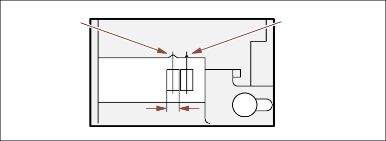
Example for 8mm S feeder modules 3
Fig. 3.9 - 1 Pick-up position for components > 3 mm or </= 3 mm
Æ Check to see if all the plugs of the feeder modules are plugged in to the correct sockets.
Pick-up position
Pick-up position
> 3 mm
for components
≤ 3 mm
for components
Width